I’ve been trying to take over control of my home’s central heating using a combination of software and commodity hardware such as the Arduino and Raspberry Pi. Part one of this series looked at how my existing RF thermostats worked and showed it should be possible to emulate them so that the receiver (which has relays that turn heating zones on/off) already connected to the boiler could be used by my own control system. I currently have two Danfoss TP7000-RF wireless thermostats (one per zone) and a Danfoss RX2 receiver.
In this part, we look at programmatically receiving and transmitting packets from/to the Danfoss RX2 receiver in order to turn the boiler on and off, and start to look at how this could be integrated into a more complete system.
The RF69 radio module
In order to be able to transmit and receive thermostat messages, we need an FSK transceiver that can receive and transmit packets of the right format. The RF69 family by HopeRF is a popular module used by enthusiasts; typical use cases include creating networks of home automation devices and sensors. There are various libraries that make use of the packet format features of the module, or layer a packet format on top, to provide bi-directional communication. However, in our case we need to integrate with the non-RF69 receivers/transmitters used by the existing installation. This is possible: the RF69CW supports up to eight sync words, fixed- and variable-length packet formats that are flexible enough to receive packets in the format transmitted by the thermostats, and supports the 433MHz frequency.
One minor issue is that the data sheet claims that the minimum supported data-rate is 1.2kbps, however my experimentation shows that it can deal with the 1000bps rate used by the Danfoss thermostats.

There are a variety of hardware options for incorporating the RF69 into your project:
- Connect the RF69 directly to a Raspberry Pi: You could make up an interface board yourself or buy a PCB with the correct headers and pads for the RF69 and Pi (or facility to add them). This has the downside of only working on a Pi.
- OpenEnergyMonitor’s RFM69Pi module, which is an Arduino-compatible Pi “hat” including an AVR chip and the RF69 module on board. You can easily upload new firmware to it for this project; I think it is well-suited though mine is currently busy in my energy-monitoring setup. This approach shares the downside of requiring the Pi to operate it.
- The JeeLink v3c by JeeLabs, which combines an Atmega 328P and RF69CW module into a USB form-factor that’s Arduino-compatible. Be sure to purchase the 434MHz version.
I went with the JeeLink option as it’s a USB device so can be used easily both with the target Raspberry Pi as well as a traditional PC for development.
Firmware
The firmware used in this project is available on GitHub under an MIT license.
The first thing to deal with is interacting with the RF69 module. There are a number of existing projects that implement libraries for RF69, though I decided to write my own because the others either didn’t quite fit my needs or had application logic embedded in the code. Both JeeLib and Mad Scientist Labs, whose work served as a useful reference here, deserve shout-outs. DeKay’s posts at Mad Scientist Labs on reverse-engineering a Davis weather station are a fascinating read.
Some specific requirements we have for this project:
- The sync words: We’ll need to use the six encoded sync words that the thermostats transmit (
0x6cb6 0xcb2c 0x92d9, which decodes to0xdd46). These come after the preamble; the RF69 normally uses a raw10101...pattern as its preamble, but can be configured not to send one and seems to lock on to the transmission just fine even with the encoded version of that pattern being used by the thermostats. - The packet format: The RF69 supports whitening and Manchester encoding, checking and embedding CRCs, and variable-length packets (where the length is indicated in a byte contained within the packet). We want to disable all these features: we use fixed-length packets, and receive the encoded packet into the Arduino firmware where we will decode them.
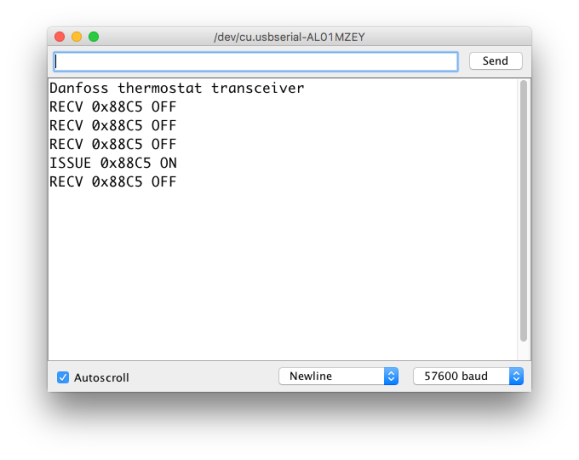
We want to provide a serial interface, emitting a line per received message with the thermostat ID and the command that was sent (on, off, or learn), as well taking commands as input to tell us to transmit packets with a particular thermostat ID and command. I’ve tried to keep it machine- and human-parsable: the sketch I provide takes input of the form XTTTT\n, where X is the command (O for On, X for Off, and L for Learn), and TTTT is the thermostat ID in hex. It prints lines like <RECV|ISSUE> TTTT CMD where RECV indicates that a packet was received or ISSUE is a command we just issued, TTTT is the thermostat ID, and CMD is either ON, OFF, or LEARN.
Encoding and decoding to/from the wire format
Encoding and decoding on the Arduino with the RF69 is simpler than in part one where we were using the wave file from the SDR because, once the RF module is programmed with the correct bit-rate etc., it does the data slicing and bit synchronisation for us.
The representation of a bit in the encoded packet has a preceding 0 and trailing 1, and the middle bit is the unencoded value being transmitted (this is a simple technique to ensure the signal is constantly being modulated so that the gain on the receiver remains within usable bounds).
To decode, we set bit i of the output according to bit 1 + 3 * i of the input (counting from left to right in the binary representation, so bit 0 being the most-significant bit of the first byte of output). Similarly, on encoding we copy bit i from the input into bit 1 + 3 * i of the output, inserting the preceding 0 (at bit 3 * i) and trailing 1 (at bit 2 + 3 * i. You can check out the sketch to see details of how this is done: the encode_3b and decode_3b functions are the relevant place to look.
Receiving packets
The receive code gets a packet of data from the RF69 and has to decode it, validate it, and extract the instruction and thermostat ID. The thermostats retransmit the packet immediately, so the received packet has the sync word stripped off the first copy of the packet by the receiver but both it and the preamble are present in the second copy as passed to the micro-controller.
One annoying issue that there is a stray 0 bit in-between the first and second transmissions. As a consequence the overall data is not a whole number of bytes, which is a problem because the packet length is specified in bytes to the RF69. I experimented with programming the receiver to get the last byte, of which only the first bit is transmitted, but this causes problems such as the reported RSSI value being useless since the thermostats don’t transmit anything for 7 of the 8 bits in the last byte. The sketch instead specifies a packet length that is the number of bytes rounded down and works around the missing bit at the end of the transmission.
To receive a packet we do the following:
- Get the packet from the RF69’s FIFO into an array;
- Shift the second copy of the received packet left by a bit so we can do direct comparisons between the two copies;
- Decode the packet;
- Validate the packet: check that the sync word is correct in the retransmission, and that the thermostat ID and command match in both copies (being sure to account for that missing bit);
- Extract the thermostat ID and command.
If valid, the received data is then output to the serial console.
Transmitting a packet
Originally I’d hoped I could use the RF69’s preamble and sync word features for transmit also, but this would require the receiver to accept packets of a slightly different format than it sends. Having tried this and found it not to work, the sketch instead closely emulates the thermostat’s packet structure.
During transmission we have to temporarily turn off the sync word feature of the RF69 in order to produce a packet with the custom preamble, followed by the sync words, the data, and then a repeat of the packet (the repeat doesn’t seem to be strictly necessary and therefore could potentially be handled more simply but I decided to maintain a close emulation anyway). The RF69 library I wrote has support for temporarily disabling the sync words and using a different packet length than for receive.
Other than that, the transmit sequence is pretty simple: parse the command from serial, generate a thermostat packet (including preamble and sync words) with the appropriate values included, encode it to the line-encoding used by the receiver, put it in the RF69’s FIFO, and then transmit it.
The higher-level control system
So far we’ve provided a basic mechanism to turn on/off heating in a zone. There are many options for how this can be used to achieve the features you’d expect from a heating control system. Some characteristics of such a system might include:
- It has inputs in the form of current temperature readings;
- The available temperature data will be used to decide when to turn on/off heating in a zone;
- There is a scheduling mechanism, choosing at what times specific temperatures should be targeted;
- A way to see the current temperatures, the current state of the boiler, the target temperature, the schedule, etc.;
- Safety features. In particular, what happens if the control system, the devices providing temperatures (or those receiving them), the radio module, etc., fail? What should the desired outcome and recovery be in these cases?
- Being able to set a desired temperature and have the system automatically start heating earlier to reach the target temperature at the requested time;
- Outside temperature and other factors (such as other heating sources interfering with the feedback mechanism) are inputs to the system to enable it to optimise central heating use.
Implementing all of the above is pretty large undertaking (not all of which I have yet done!) but would essentially provide an implementation of a domestic-grade heating control system.
By aiming to create decoupled components with clear interfaces we can enable substitution of alternatives suitable for the specific installation. For example, users without Danfoss thermostats may wish to replace the component described in this and the previous post with their own system for turning on/off heating in a zone (e.g. using relays directly attached to an Arduino, or interfacing with a different RF receiver).
What’s next?
Future articles will examine the behaviour of the Danfoss system further and look at when it is turning heating on and off in response to input, and start to implement the higher level control mechanisms described above.
Code
The most up-to-date code including the sketch to implement the interfacing described in this article is available on GitHub.
