Categories
Uncategorized

Being a Beginner: Running your first Half Marathon

In March 2023 I ran the Cambridge Half Marathon. It was my first half marathon. I wanted to do something worthwhile and that was bigger than myself. I raised almost £1000 for Mind in the process, and also improved my mental health by having a non-work goal to strive for.

I’m still firmly middle-to-back of the pack when it comes to racing, but I did beat my own goal by achieving a time of 1 hour, 47 minutes, and 48 seconds (my target was to beat 1:55:00).

Afterwards, a friend, who turned out to do relatively even better in their respective race, asked for some tips and how I prepared. Since I’d already written this up for them, I figured I’d post it as a blog post. There’s obviously a lot of guides and how-tos for this, although I’d say only a few are written from the perspective of someone new to sport, so hopefully this gives a slightly different perspective.

The regime

My starting point was being reasonably used to running, including some distance – I’d done 21k before but it took over 2h – and had eight weeks available for specific training.  I ran 3-4 runs per week, ramping up from 25km per week up to 45km per week near the end. Here’s some of the principles/ideas I followed for my training plan and preparation:

Include lots of low intensity distance: A lot of coaches advocate for doing a significant amount of training at lower intensities.  You can search for MAF training, 80/20 training or various others.  I’m not sure this directly translates from pros to amateurs (especially the 80% bit), but I followed the general principle and did a lot of distance at low heart rate (around 140-145bpm for me).  This helps to get the training volume/distance in and the aerobic fitness benefits without risking injury or causing excess fatigue that stops/slows down later training.  I definitely saw the paces I achieved at these heart rates improve over the training block.

Include pace/workout variety: Along with the above, it seems widely accepted that doing a variety of paces during training is recommended.  My training included:

  • Slow runs (targeting low HR, 140-145 bpm – maybe just under 6:00/km for me).  These started around 6.5km up to 19km for the weekend run.
  • Interval sessions: maybe the best one but it was very taxing was 6x800m progressing from 4:50 down to 4:20/km – or a bit slower than your best 5k to a bit faster with 800m slow jogging between).  This is apparently good for increasing lactate threshold, VO2 max, and speed generally.  Another session I tried was 6x [2 mins almost the fastest I could do (around 4:10/km for me) + 3 mins jogging recovery] with warmup and cooldown.  I’m not sure how effective this workout was for me (fast parts too fast, requiring too much recovery to maintain in between and not getting the average HR high enough, maybe).
  • Progressive runs (e.g. 8km starting at 6:00+/km and speeding up every 1-2 kilometers up to sub-5:00/km for the last one). Good for getting experience speeding up or not slowing even when your legs are tired.
  • Long runs: some were low HR, others incorporate another workout within them.  To not overdo training intensity, I alternated these each weekend between a slow one and one that included one or more tempo (moderately-hard) sections.  When I started, I was exhausted after the tempo version that was 16km at 6:00/km with the middle 5k speeding up to 5:15/km.  Later I did one that was 3x(3km @ 5:15/km and 1km slow) + warmup/cooldown, this also felt exhausting at the time but was clearly showed improvement on the previous one.  Both were slower than my final race which was 21km at 5:06/km average.

Nutrition: For the race itself I used High5 energy gels. I took my own and avoided aid stations as they were crowded. I don’t particularly like using a lot of “fake” nutrition but it’s needed when you’re working hard in the race (as I found out when I ran out of energy on an early training long run), and it’s also worth practising on the long runs.  I would use 1-2 on long training runs, and had 3 during the race. Practising helps you to find ones that are compatible with your digestive system and can consume easily whilst running.

Sleep: Is generally considered important for proper recovery from difficult workouts, and I can definitely agree that my performance is better after proper sleep than otherwise.  Related to this is that alcohol disrupts sleep, even a single drink can make a notable difference.  I cut out most alcohol for the duration of my training.

Taper: Slowing down training close to a race can make a big difference –I reduced volume by 30% starting two weeks before and only did low-intensity + 1km fast at around 30% of maximum distance in the 7 days leading up to the HM.  I am very sure this made a big difference for me: some people say they feel niggles more in the taper period as healing/recovery happens, and I certainly noticed this/was worried about it, but I was totally ready on the day.  For longer training blocks I’ve heard people insert “recovery weeks” periodically, although in my case I think I didn’t have enough time to make this work.

Equipment

I really tried not to buy anything fancy.  I didn’t want my running to become about having fancy kit and spending money.

Watch: My running watch is a second-hand Garmin Forerunner 245.  It’s great and nothing fancier is needed, but it’s definitely worth having a watch suited to this as I found my Fitbit (daily watch) to be unreliable and inaccurate.  Conversely, the Garmin is a bad daily watch because it has the worst sleep tracking out of Fitbit/Google and Apple.  That being said, I didn’t buy the watch until after over a year of just using my phone.

Shoes: My shoes are Altra Escalante Racer (which are good if you’re used to barefoot shoe-style walking, otherwise you probably want to find something different as these have no heel rise) at around £115/pair (though they don’t last well, I start mixing in a new pair after around 500k and they’re dead at around 800km).

Foam roller: I got this when I had a bit of calf soreness and a friend said it worked miracles when they had similar issues.  I would agree and I got an AmazonBasics one for <£20.  That being said, I also was careful not to overtrain, and generally increased intensity by no more than 10% per week or between comparable sessions.

Otherwise, I have shorts from Amazon (<£20/pair), technical running underwear (I got wool-rich ones but they aren’t available anymore), and basic technical T-Shirts (I’ve been using walking ones I’ve had for many years…).

I subscribe to Strava but honestly it’s not that necessary.  Garmin Connect, the free app that you get access to with their watch, has almost everything that Strava does apart from the social aspect of it.

Conclusion

The main thing that I didn’t do that i think would’ve helped was some kind of strength training for core and legs, which I’ll probably look into for future.

I hope this gives someone a helpful start. Post how you trained for your first half in the comments, or feel free to ask questions!

Categories
Uncategorized

Smart under-cupboard kitchen lighting

Our kitchen is almost 10 years old now. When we first had it designed and installed, I totally underestimated how important good task lighting was, but thankfully the designer knew better and included a set of under-cabinet lights to illuminate the work surfaces. The lamps in these faded, were replaced and the replacements starting failing, so now it’s time to take on installing some nice smart lighting to make things even more functional.

Image showing old lighting, with dark and light areas caused by spot lights.
The old lighting (excuse the temporary backsplash behind the cooker!)

I’m a big fan of dimmable lighting to set the mood at night and reduce eye strain that also can provide practical lighting for tasks when needed. I also enjoy lighting that has adjustable white points since lots of blue-light exposure at night seems to be correlated with lower sleep quality.

I decided LED tape and a semi-custom installation (separate controller/wiring, but not going so far as coding up my own controller via Arduino or similar) was the way to go as it has grown in popularity and maturity over the last few years. I’ve replaced all the light fixtures with a set of three cool-white/warm-white adjustable strips from LEDspace and then used a ZigBee controller to connect it with the Phillips Hue bridge I already have.

Here’s the story of the outcome and what I did.

Was it worth it?

I’d say a qualitifed “yes”. I like that the LED strip eliminates bright/dark areas that we had with the old GX53 fittings. I like being able to dim and adjust the lighting, but…it’s also a bit of a chore. I think the real value in this kind of installation comes from automation. The smart controller we used works well with Phillips Hue, though it doesn’t seem to have the “on startup” configuration and instead will switch on the whatever the last setting was. The 9W/m tape I used is just about bright enough, but I have a niggling wish for a bit more brightness. In total we have 3m of 9W tape, so 27W, compared with 7×4.5W lights before for a total of 31.5W.

After the novelty has worn off, I at least personally won’t be manually adjusting the lights on a regular basis. Unless you’ve made all lighting in the room smart, in which case you can use a scene switch to replace rather than augment the standard light switch (and even then, retrofitting is going to be non-trivial), it will need to work correctly with the existing switching. The options for manual switching are voice (via Alexa/Google/Siri), app (e.g. the Hue app), or a separate scene controller (such as the Hue remote; but then this introduces annoying user experience issue from the interaction with any existing switching).

I’d like to do two things in future: get smart control on more of the lights in the kitchen and dining area to make scenes (set via either Alexa or a remote control) more functional, and also consider integrating presence sensing to dim the lights automatically.

Getting started

The first hurdle was to figure out the wiring. Having decided I wanted a colour-temperature controlled LED strip, I knew I needed three wires to the LED strip. The existing installation consisted of a set of lights and a light on its own, switched from one place. The light on its own was fed a switched mains in a 2-core-and-earth cable from a junction box near the group of lights. The group of lights were fed the same switched 240V mains supply and were connected via a splitter with custom sockets that fed each light fitting.

Choosing an LED strip type

Choosing the type of LED strip can increase or decrease the complexity of the wiring. I was able to perform the nasty hack of re-using the mains cable that was already fed through the walls to the second location as a 24V supply with two rails (for warm and cool white), since the 24V doesn’t require a double-insulated cable which means I could use the wire normally used for earth in a mains setup as one of the rails. The LED strips options you can choose are:

  • Fixed white: This is the simplest option. You can buy a fixed colour temperature LED strip, which would require a simple two-wire connection. It’s probably the most flexible in terms of frequency of cut-points, manufacturers, and varieties such as splash-proof and “spot-free”/chip-on-board. Since these are widely available you can get brighter strips easily and with good colour rendering indexes (CRIs). The CRI describes how much of the colour spectrum is emitted by the light: higher values mean better reproduction of colours under the light.
  • Colour-temperature changing white: This is the option I went for. Like the single-chip type white strips these are dimmable but have two colours of LED (cool and warm white) that can be used in combination to make a broad range of colour temperatures. They typically require three connections (+24V, warm white, and cool white). Since the extra chips take up physically more space the cut points seem to commonly be less frequent: the strip I have can be cut at 100mm intervals instead of 50mm on many of the single-temperature strips.
  • RGB: These have LEDs that can emit different intensities of red, green, and blue to make a full range of colours. They typically require four connections, can often be less bright than similar white strips and don’t render whites as nicely as a dedicated white strip. For the kitchen task-lighting I was installing I ruled out this type of strip because I wanted to optimise for good white rendering. Also in my case I needed to re-use an existing three-core cable.
  • RGB-W and RGB-WW: These are like RGB strips but also have either one or two dedicated white LEDs to make the rendering of whites as good as regular white-only strips. They’re the most expensive and complex, requiring either five or six connections.

Powering and controlling the LED strips

The LED strip will require either 12V or 24V power, depending on the type you chose. Mine required 24V. You can wire many LED strips in parallel since each group of LED chips between the cutting points are in parallel on the strip. Wago connectors to join all the wires of the same type seem to work well and are easy to install.

A common wiring would be a power supply to convert 240VAC mains to 24V, then a controller module to do dimming and colour temperature control, and then each strip wired in parallel. In my case, I was able to wire all the strips to the controller directly so they appear as a single light in the Hue app. If you aren’t able to do that, for example if you have some strips that have a separate power supply, then you can always use multiple transformers and controllers though in this case the LED strips will show up as separate lights in the Hue app. This is pretty normal for Hue though: lights can be grouped and controlled together and this model works well, so even if it might be more expensive it’s a reasonable approach if you need it.

Here’s the wiring diagram I posted on top of the cabinets next to the wiring for my installation. Nothing’s perfect, so I left the warts unhidden here: I ran out of black/red/white three-core cable so had to switch colours partway through, and I also re-used a mains cable as a 24V supply since I couldn’t re-pull more obvious cables through and felt that buying a separate transformer and controller just to avoid this wasn’t worth it.

Wiring diagram

Physical installation

In my case, the physical installation wasn’t particularly tricky. I turned off the old downlighting, checked it wasn’t live, and removed it. I was able to do this in stages — having a young child limits how much time you get to work at once on these things! — by temporarily powering the transformer for the partially-installed new lights from the splitter that was part of the original installation, alongside the remaining old light fittings. The old fittings were screwed onto the bottom of the cabinets, and I was able to reuse the screw holes for the clips that hold up the aluminium profile that houses the new strips.

Wiring

There are friction-fit connectors that you can use to wire up the strips, or do as I did and simply solder the wires onto the pads. I’m not new to soldering, but I did have to remember some tips from the years ago when I last did it: heat up the pad and feed the solder onto it, use enough solder but not so much it bridges to another connector (I was using a particularly fine reel of solder intended for surface-mount work, so was prone to using too little), twist the strands of wire tightly together by grabbing it at the very end and rotating it, add solder to both the pad and wire before re-heating the pad and joining the two to tack it into place and, finally, check your connections using your multi-meter’s audible continuity testing feature.

A join of two LED strips at 90 degrees
Corner fitting

I had a corner to deal with, and decided to use a corner-connector to get a very tight, clean connection rather than attempting to solder wires at 90º. This worked well although the connector did not fit into the aluminium profile I had, so to fit it I had to first measure and cut the tape, connect it at right angles, solder the wire connection onto one side, and then finally remove the backing tape and stick it onto the aluminium profiles held at a right angle. I assembled the two pieces before installing it into the retention clips. Determining the lengths of these strips and getting the profiles cut to the right length seemed daunting initially, but was pretty easy once I realised that I had around 5cm wiggle-room on length, and that the position (depth into the cabinet) was already determined since I was using the existing screw-holes cut for the previous fixtures.

Housing

I used the adhesive tape on the LED strip to fit it into aluminium profile. This has a diffuse plastic cover that can be applied to reduce the appearance of spotting; it also helps to remove some harsh shadows from the edges of the LEDs. I was originally concerned that fitting the strip into the profile might reduce the angle of light emitted, but it turned out not to be a problem. The profile and covering can be cut easily using a hacksaw.

Don’t forget, like I did, that the aluminium profile is conductive, so make sure you tape over your contacts before test fitting the strips. Luckily, the controller had overcurrent protection so shorting it didn’t cause any permanent damage.

ZigBee controller

Gledopto LED dimmer/ZigBee controller
LED controller

The ZigBee controller I used is the Gledopto WW/CW controller. It integrates well with Phillips Hue and works pretty flawlessly in the app. As mentioned above, it doesn’t support an ‘on startup’ setting, but other than it’s no different than the other Hue lights I own.

Parts and tools

Here’s a list of parts I used:

Tools you will probably need include:

Conclusion

Rubbish bag with old lighting parts in it.
Got rid of quite a lot of stuff when taking down the old lights

Overall, this was a fairly simple, fun project and is an improvement over the previous lighting setup in the kitchen. The main thing I’d consider doing differently is to consider a brighter LED strip, but other than that it’s working nicely.

Thanks for reading! I hope this was helpful if you’re considering a similar project. If you have questions or want to learn about my future projects, follow me on Twitter for more.

Categories
Uncategorized

Everything you need to know about integrating Google Sign-in with your Web App

Investigating Google Sign-In led me down a rabbit hole of trying to understand authentication with Google, how it fits with standards such as OpenID Connect (OIDC) and OAuth 2.0, and how best to integrate it into a web app that has a JavaScript frontend and backend API.  This article is the result of that research.

On the face of it, integrating with Google Sign-In is trivial: there’s a Google page that tells you how to do it.  But I believe in understanding the tools you’re using rather than just pasting code from random websites, especially when it comes to security-related functions.  I wanted to understand what was happening under the hood and be sure that I wasn’t inadvertently introducing security holes into my app.  So I created a simple sample app that has just enough function to demonstrate how to safely integrate sign-in to your app.

Check out the sample Hello app on Github that demonstrates the topics discussed in this article.

The app

helloapp3

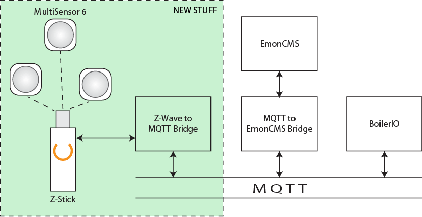
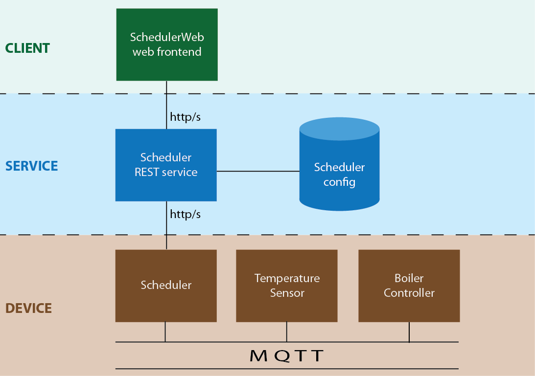
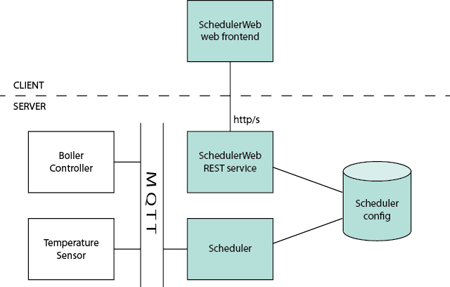
The demo Hello app is a React-based web app that talks to an API assumed to be in the same domain.  The app that led me to start this work — the BoilerIO open source heating controller — is very similar: it is close to a single-page app (I’d say it is one, but the definition of an SPA is a bit vague so I’m going to avoid absolutes here) with a JavaScript (React) frontend, and an API it interacts with (intended to be hosted in the same domain) written in Python using flask. The goal is to add login to the app using Google Sign-In.

In the BoilerIO app I wanted to restrict login to a set of known people, authorised by an administrator, but this probably isn’t the common case so I’ve not included that in the sample Hello app.

When to use this approach

Authentication and authorisation can get complex when your application needs to deal with multiple identity providers, and even more so when you’re dealing with non-cloud identities.  The scenario we’re dealing with is one of the simplest: a single, cloud-based identity provider aimed at consumers (“social sign-in”).  If you have a more complicated scenario — your own username/passwords, multiple providers (Google Sign-in, Login with Amazon, Facebook, etc.), or enterprise directory services (e.g. Active Directory) then it gets a whole lot more complicated and you might instead use a service like Amazon Cognito or Auth0 to do the hard work.

This doc is about Sign-In specifically: you might also want to get authorization to use resources that the user owns in the third-party domain, for example getting access to their Google Drive or Calendar for use within your application.  There are additional considerations in this case around security of the tokens and choosing the right flow for your application that aren’t covered here.

We’re using the Google SDK to do sign-in, with a lightweight wrapper in the form of the react-google-login frontend library.  This is a good choice if you want just Google Sign-In.  If you want to support multiple providers then you could still go this route (other service providers such as Facebook have their own SDKs too), or you could use a service that gives you multiple options via a single interface (such as Cognito mentioned above), or use a generic OpenID Connect implementation for the providers that support it.  Using the SDKs removes some complexity and therefore (hopefully) security risk from your implementation.

How does Google Sign-In work?

Google Sign-In via the SDK is built on Google’s OpenID Connect (OIDC) implementation.  It uses extensions to this, the so-called “Identity Provider (IdP) IFrame”, so some of the recommendations for securely implementing OIDC don’t apply directly.  The “IdP IFrame” mechanism was described in a draft RFC published to the OIDC mailing list, but I wasn’t able to find any follow-up to this, and it’s likely that the implementation has progressed since that draft was published.

The SDK provides a signIn method that you can call as well as a way to generate a button the user can click on that is equivalent to calling this method.  This initiates a user flow that, by default, pops up a window to allow the user to authenticate to Google.  This will ask them to give permission to your application for the “scopes” you have requested if they haven’t already provided this permission before.  Scopes are the things that you are requesting access to; in the Google console you can select which scopes your credentials are allowed to be used for, and you should pick the smallest set possible.  For a sign-in use case, you only need to ask for “openid”, “profile”, and “email”.  You could also get access to the user’s Drive contents, Calendar, or other resources, by adding appropriate scopes here.

Once the user completes the sign-in process your application will receive back an access token, a refresh token (if the “offline” type was selected), and an ID token.  The ID token is a JSON Web Token (JWT) that contains claims about the user’s identity.  Your API must validate this (since a malicious user could easily inject a fake JWT) and then it can be used as proof of the user’s identity.  Within your app, you can treat this a bit like a correct username and password.

The other tokens aren’t as relevant for sign-in/authentication use cases.  You can use the access token to access Google resources belonging to the user in the scopes that you requested.  If you only specified the limited scopes suggested above, this will give you access to the userinfo endpoint, which can be used to obtain information about the user the access token was generated for.  The information this provides is a subset of that in the ID token you already received.  All of these token have an expiry, but the refresh token has a longer expiry than the others (typically) and can be used to get new tokens.

The client-side Google code for the SDK is closed-source (or, at least, I couldn’t find the source) so it’s hard to say exactly what it’s doing, my guess is it’s using a grant similar to the Implicit OAuth grant, but with some additional security bought by use of its own code within the IFrame and the way it gets the credentials to the calling application (using HTML5 local storage as a relay between the Google-originated IFrame/authentication popup and the client application, rather than via a redirect as would be used in plain OAuth 2.0).

Adding Google Sign-In to your application

When adding authentication to your application, you’ll need to:

  1. Create OAuth credentials in the Google API console (since this is used in the Sign-In process).
  2. Add flask-login to your app to manage user sessions.
  3. Add authorization checks to your existing service endpoints.
  4. Implement some way of storing users and representing them, and then link this with flask-login.  Typically this would be in a database.
  5. Implement endpoints to log users in and out and to provide information about the user to your frontend/client.
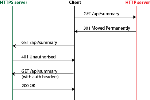
  6. Modify your frontend/client(s) to check for 401 (Unauthorized) responses from your server, and offer the option to log-in when these are received.
  7. Add a login page to your frontend application.

We’ll go through each of these in turn, and each section will cover in more detail what you need to do along with pointers to the sample Hello application.

Creating OAuth Credentials for your service

What do I need to do?

  1. Go to the Google API console and create OAuth credentials for your app.  You can choose the “Web app” option when creating the credentials.  You’ll also need to configure your “Consent screen” if it’s the first time you’ve done this.
  2. You only need the Client ID when using the Google Sign-In SDK: expose this through configuration to your frontend and backend.

In the Hello app: The Client ID is exposed through the GOOGLE_CLIENT_ID configuration entry in the Flask backend.  We use Flask’s standard configuration support to load configuration from a Python file named in the environment (HELLO_CONFIG).  Although it’s not a “secret” the client ID is still better handled through configuration than being checked into the code.  In the React application, we use an environment variable (REACT_APP_GOOGLE_CLIENT_ID) in the .env file.  This is built into the distribution at build-time and visible to clients.

The Google Sign-In SDK uses OAuth under the hood, and you need to pass it an OAuth Client ID for your application.  You can create this as in the Google APIs console.  Some of the choices available when doing so are:

  • Application type: Google limits what can be done from certain client IDs, for example which OAuth 2 flows (implicit grant, authorization code) can be used.  You should select “Web client” here.  It’d be nice to see Google publish more details about what these choices allow/disallow; for example, for a website with a backend it might provide more security if you could require that the auth-code flow is used.
  • Authorized JavaScript Origins: These restrict where Google’s authentication flow can be initiated from.  You should put any origins that you host your site from, including localhost for testing, here.  You’ll need to provide the full origin including protocol, hostname, and port.
  • Authorized redirect URLs: Leave this blank.  In a normal OAuth flow, the identity provider uses a redirect back to your site to get credentials to you (the access/refresh token).  When you’re using this Google Sign-In SDK, this happens outside your application using the storagerelay URI scheme, so there is no redirect back to your site.  As a side-note: If you step outside the sign-in flow discussed here and use OIDC directly with the Auth Code grant type then, if you’re getting your token from the token endpoint, you need to specify the same redirect_uri parameter in both calls (for the code and the token) and you might want to set this to postmessage rather than an actual URI if you’re getting the tokens from the token endpoint rather than a redirect.

As an aside, localhost is a valid option for the URLs above if you’re using a standard OIDC/OAuth flow rather than the Sign-In SDK because the redirect is handled by the user’s local browser and so localhost refers to the user’s host in that context.  You will want to include that when testing your service locally.

If you make changes to your OAuth credentials (such as adding a new authorized JavaScript origin) it can take several minutes (sometimes over an hour) for this to propagate to Google’s servers, so be mindful of this when testing updates to settings.

Adding authorization to your service

What do I need to do?

  1. Add flask-login as a dependency to your application (using pip install or pipenv if you are using this for package management).
  2. Add the login_required decorator to all methods that should require the user to be logged in.
  3. Create a secret key for your app to use when signing sessions.

In the Hello app: The flask-login dependency is in the Pipenv file.  In app.py we instantiate a LoginManager at the start.  The secret key is part of the configuration.

For a single-page app on the same domain, the flask-login extension to Flask helps you to implement session handling in your backend.  Flask-login lets you implement your own logic to authenticate a user, but does the work of managing the session and cookies for you.

You will provide a “login” endpoint that validates the credentials provided and sets a session cookie (using the login_user method provided by flask-login).  This cookie is then passed on each subsequent request, validated by the flask framework for you, decoded to determine the currently logged-in user, and the user information is available to your application code via the flask.current_user variable.  You can also decorate your endpoints with the @login_required function to ensure that only logged-in users can access them.

You can treat a valid ID token from the identity provider as equivalent to a username and password: your “login” endpoint takes this ID token, validates it, and logs the user in if it is valid.

Flask sessions include a message authentication code so are tamper-proof, but are not encrypted (see the documentation).  They’re also stateless, so there shouldn’t be any concern around horizontal scaling of your service.  Flask by default (as of writing) uses the HMAC-SHA1 algorithm, so a key length of at least 160 bits (20 bytes) is desirable.  As noted in the Flask documentation, you should generate this from the os.random function.  To improve security, we set “session protection” to “strong” in the login manager, which prevents the session cookie from being used on a different host, and set the “Remember me” cookie to have the HttpOnly flag so it can’t be read by client JavaScript code.  You could also add the “secure” flag to these two cookies, so that they are only sent over HTTPS (and not HTTP) – you could consider doing this in your production configuration but not in the testing configuration to make development easier.  Setting HttpOnly prevents code on the client accessing (and therefore potentially leaking) the session token.

Why not use JSON Web Tokens (JWTs)/bearer tokens, passed via the Authorization header on each request?  Doing so is actually pretty similar to the sessions approach described above, except that a JWT is used and passed in a different HTTP header: both are tamper-proof, unencrypted, encoded blobs of data.  The origin of the JWT could be your application (generated in your login method, then passed by the client on subsequent API calls) or the JWT given to your application by the identity provider.  This method isn’t the recommended one because, in the case of handling your own JWTs there’s no advantage over using Flask’s built-in session support, and it has the disadvantage of requiring additional code or dependencies in your application.  Because JWTs can be large and need to be passed in the Authorization header, you can’t store them in an HttpOnly cookie and your client code has to handle them.  In the case of using the Identity Provider’s (Google’s) ID token (which is a JWT), the main issue would be that this is short-lived so you’d have to call the Google Sign-In SDK again to get a new token.

Managing users

What do I need to do?

  1. Implement a way to store and retrieve user information, “user loader” (a method that looks up a user by ID, called by the flask-login code), and “User” class with at least an ID attribute.
  2. You’ll also need a way to log users in: see the next section for more information.

In the Hello app: The UserManager class in the Hello API implementation is a trivial in-memory store of users.  It’s keyed by Google Subscriber ID: In your application it is probably better to store a synthetic primary key as a user ID and use this to identify users.  This gives you flexibility later to add other authentication providers.

The load_user method is decorated with the LoginManager instance’s user_loader and does a lookup of the user ID passed to it.  This will be called when a valid session cookie is received containing the logged-in user ID to get the full User object back.

The User class uses the UserMixin to provide basic requirements; note that you must implement an id property.

Typically you’ll have one or more database tables to represent users.  It’s worth considering that you might want to allow the same user to sign in with different providers or credentials in future (username/password, Login with Facebook, Login with Amazon, Google Sign-In, etc.).  Each provider will give you a “subscriber ID” (the sub field in the identity token) as part of the user’s identity that is guaranteed to be unique for that identity provider (see the OIDC standard, which says that the subject identifier is a “Locally unique and never reassigned identifier within the Issuer for the End-User, which is intended to be consumed by the Client.”).  So, a simple solution could be a column per ID provider.  The article Merging multiple user accounts by Patrycja Dybka suggests a more sophisticated alternative, based on what the StackOverflow site does, using a separate table to store the user identities, as well as discussing how this could be presented to the user.

You should consider how to deal with users logging in using the Google Sign-In feature that have not used your site before.  The Hello app example doesn’t deal with this, but you could return a value to your client to indicate that additional user information is required in this case if needed.

Implement “login”/”logout” endpoints for your backend

What do I need to do?

  1. Extend your API to facilitate login/out.  You could consider using the google_token module provided in the Hello app to do your token validation.

In the Hello app: We expose a single endpoint (/me) which has a POST method to log in using an ID token, a GET method to retrieve information about the currently logged-in user, and a DELETE method to log the user out.

To validate the ID token, we provide a convenience method that calls the Google Python SDK: this is a trivial wrapper that creates a CachedSession object that the SDK will use to make outgoing HTTP requests.  By using the cachecontrol library here we honour the HTTP headers when implementing our cache (so that, for example, Google’s key rotation will not cause our logins to fail, but also we don’t cause outbound traffic to scale with calls to our login function).

The login endpoint validates the user credentials (the ID token provided by the Google Sign-In process) and either logs the user in (sets session cookie by calling the LoginManager’s login_user method) or returns an error (403 Forbidden).

To validate the signed ID token, a number of checks must be made.  This is all done for you through the Google SDK.  The Hello app has a convenience method you could copy in the google_token module that deals with caching outgoing HTTP requests.  The checks in summary are (i) validate the signature using Google’s public keys (which need to be fetched from the correct Google location), (ii) check that token has not expired, and (iii) check that the token was intended for your application (so that a token intended for another application cannot be injected).  You can find out more about these checks in the Google documentation.

Adding a login page to your client

What do I need to do?

  1. Import the Google Sign-In SDK.  In our React app, we’re using the react-google-login npm package.
  2. Implement a login page.
  3. Redirect to the login page when you get Forbidden responses to API calls on the client

In the Hello app: We use the react-google-login package.  The main page uses a HashRouter to implement navigation between pages of the app.  There are two pages: the main “Hello” page and the “Login” page.  We implemented the ProtectedRoute component to encapsulate logic to redirect to the login page if the user needs to authenticate.  In the main app we also use an AppBar with a profile icon that the user can click to log out, to demonstrate using information from the user’s profile.

Once you’ve implemented authentication on your service, modifying the client to authenticate should be relatively easy: in React we do this by keeping some state that indicates whether the user needs to be authenticated.  When an API request fails with an error indication lack of authorization, this state is updated indicate that authentication is required.  When authentication is required, we render any “protected” pages as redirects back to the login page.

Similarly, if the user is authenticated already we redirect to the homepage.  Some clients would take a slightly more sophisticated approach by keeping track of which page to return to after authentication is complete.  If you’re doing this be careful not to introduce open redirect bugs (see the OWASP cheat sheet on Unvalidated Redirects and Forwards for more info).

The login page itself includes the Google Sign-In button, and a handler to send the ID token we get handed to our backend for validation and to sign the user in.

Add cross-site request forgery (CSRF) protection

What do I need to do?

  1. Any mutating operations need to be protected with a CSRF check: a simple option is to use the X-Requested-With header.

In the Hello app: The Hello frontend app adds X-Requested-With as a default header sent by Axios.  In the backend, the csrf_protection function in app.py checks for the header and returns HTTP 403 (Forbidden) if it does not exist, and all mutating operations are decorated with this check.

Unless the target host explicitly allows it, browsers will block cross-origin requests as part of their cross-origin resource sharing (CORS) checks.  However, in cases such as POSTs, the call to the server is actually still made, but the result of the call is not available to the client.  This means that an attacker hosting a random site could use your authenticated session (via the session cookie) to call your API and make side-effecting requests despite the cross-origin request protection provided by modern browsers.  This behaviour is described in this excellent article: CSRF Mitigation for AJAX Requests, along with the mitigation suggested.

Adding the X-Requested-With header prevents the browser from making the cross-origin request (since this header is not allowed to be sent across origins by default) without doing pre-flight checks first.  The response should indicate that the call isn’t allowed and it will be blocked.  Adding the header is easy with axios:

axios.defaults.headers.common['X-Requested-With'] = 'XmlHttpRequest'

And to check for it in Python you can decorate your request handler with this:

def csrf_protection(fn):
    """Require that the X-Requested-With header is present."""
    def protected(*args):
        if 'X-Requested-With' in request.headers:
            return fn(*args)
        else:
            return "X-Requested-With header missing", HTTPStatus.FORBIDDEN
    return protected

How secure is this?

It depends if social sign-ins meet your application’s requirements.  If implemented correctly, then this flow can authenticate a user and give you similar confidence to that user entering a password that they are who they say they are.  But, you don’t control the sign-in flow so you’re relying on the policies of the identity provider (such as when password re-entry is required).

Using a scheme like this instead of a username/password system means you don’t have the risks associated with password management (making sure to use an appropriate hashing schemes for example).  Even still, you’re almost certainly storing sensitive information so you need to handle it accordingly.

Social sign-ins such as Google implement features such as two-factor authentication, which can increase the security of the sign-in.

When using social sign-in, the “fresh login” feature of flask-login looks somewhat questionable: often, after initial consent to allow login to your app, even logging out and then back in won’t require the user to enter their Google password as they are still logged in with Google.

Ultimately, when using social sign-in you’re not really in control of session policies since a new login can often be started without a password being entered.  For sites where this is unacceptable (you probably wouldn’t want your bank doing this, for instance) you’ll have to use an alternative.  For many sites it is good enough though: you’re protecting your application on the same basis as the user’s GMail account, which is often a high value asset.

Some (partial) gory details

OAuth 2 and OpenID Connect

There are various versions of the OAuth and OpenID standards, but the relevant ones are OAuth 2.0 and OpenID Connect.

OAuth 2.0 is a standard to enable authorization of users on third party sites (or the sites themselves) against resources on a different service: e.g. my heating app to access a user’s Google Calendar on behalf of that user.  On it’s own it doesn’t provide for authentication, but simply provides a process where a user authenticates to a third-party identity provider and allow an application access to the resources belonging to them on that site.

OpenID Connect builds on top of the OAuth 2.0 flow by specifying details of how particular flows work and what certain values that are returned as part of the flow should look like, in particular that an ID token is provided that can be validated as authentic.  This does allow for authentication of a user to your application by having them sign into a third-party identity provider such as their Google account.

In writing this article and implementation I found a lot of confusion about how these standard protocols relate to the Google Sign-In SDK.  I had assumed the Google Sign-In API provided was a simple helper to use OpenID Connect in your application (which isn’t exactly true), and therefore recommendations for the latter were relevant.  However, the SDK actually implements a customised authentication flow that extends OIDC and that relieves the developer of some aspects of the security implementation (such as ensuring that there is a unique and tracked state parameter in their authorization requests).

The IdP IFrame and storagerelay

Google’s Sign-In JavaScript SDK uses an iframe that is added to your site where Google pages are loaded to help with authentication.  There was a draft standard published for this method that I found when trying to understand why a redirect URI starting “storagerelay:” was being used.  This was published by Google engineers to an OpenID list here: http://lists.openid.net/pipermail/openid-specs-ab/Week-of-Mon-20151116/005865.html.  The iframe uses HTML5 local storage and storage events to communicate status back to your application, allowing it to use Google-controlled pages to complete the authentication without redirecting back to your site in the traditional way.

It’d be great to have more details of the implementation of the Google SDK to include in this section to be able to better understand how the security concerns compare with using one of the standard OAuth grant types, what to do if you only need identity, and how to safely avoid tokens getting onto the client.  The SDK does support the authorization code flow (which allows for this) but as far as I can see you can’t stop the non-auth-code flow being used.  Even though the main risk regarding token leakage through browser history is addressed through the IdP IFrame implementation, this isn’t well documented as far as I could find and it would seem safer to be able to prevent clients receiving tokens directly through configuration.  This is especially true if you’re using scopes beyond just ID.  The OAuth2 website describes the different grant types available: https://oauth.net/2/.

Conclusion

This article covers a holistic view of integrating Sign-In with Google to your website and hopefully gives you the confidence to do so safely.

I’m keen to make sure the content here is accurate, and that the Hello app example is secure and good quality, so please do provide comments or share pull requests if you see any areas for improvement.

Links

Check out the Hello demo app on Github that implements everything described in this article.

Google Sign-In related, and packages used in this project:

OAuth and OpenID Connect related documentation:

And finally:

  • Not the Google API JavaScript Client on github.  This repository has a promising sounding name, but is just documentation with a placeholder main.js file, sadly.
Categories
Uncategorized

Heating season 2019 is here!

Having just got back from a holiday in Switzerland (which was awesome) we got home to a slightly chilly house, and so turned the heating back on.  Although I’ve not posted here for a while, work has continued over on the Github repository for Boiler.io and there are a few new features that I’ve added that are worth mentioning.  I’ve also replaced the crusty jQuery-based UI with a nice React application.  It’d be great to hear from you if you’re interested in running open source heating software.

Why am I doing this?  Firstly, it’s a great learning exercise as my software engineering background has largely been in the world of operating systems, completely different than this kind of web/IoT application.  I hope it will be more than a toy though: as we become more and more conscious of the environment I think it’s increasingly important for technologies that help to save energy to be as open and accessible to everyone, so from enabling people to turn off their heating when not at home, through to making algorithm improvements to make boilerio more efficient will help all its users as well as provide a reference for others implementing similar systems.

Links to the software

New features

Multiple zones

Screenshot_20191227-215251As we have two floors in our house I wanted to control them independently.  In the first year of running boilerio, I only controlled the ground floor heating and used our existing system for the first floor.  Since implementing support for two zones, I controlled both floors of our house with no major issues for the whole of last winter.

Much of the changes were fairly mechanistic; one key decision was how to change the schedule representation.  The minimum to get this working would be to have two instances of the controller running with separate databases, etc.  A step up could have been to have two clients running against a single server with the schedules represented separately; this is probably a classic microservices design.  One disadvantage would be that it’s harder to co-ordinate between the clients for features like timing the on/off cycles of the multiple zones to be out of phase to reduce load on the boiler.

In the end I added zone IDs to entries in the schedule table that refers back to a new “zones” table where that zone is given a name and the temperature sensor ID that it uses.  This implies a 1:1 relationship between control zones and sensors, which could easily be improved upon in future.  The existing /schedule endpoint is now basically unused (though was updated to return a mapping of zones to their schedule) and instead there’s a per-zone zone/<id>/schedule endpoint.

Time to temperature

Screenshot_20191227-215332I wanted a similar feature to Nest whereby the heating is turned on before the requested time in order to reach the desired temperature by the requested time.  The starting point for this has been to add predictions that are shown in the UI as to how long it will take to get to the current target.


The current implementation was good to learn from but probably needs to be changed.  There is a separate program, monitor, that looks at what the boiler and sensors are doing and at the weather report (to determine the different between the inside and outside temperatures) and tries to determine the rate of heating.  It watches for periods where: (i) the heating has been on for at least ten minutes; (ii) after the first ten minute period that is ignored, it’s been on for a further continuous ten minutes and the temperature rose during that time.  We then take the duration of the interval and the starting and ending temperature to determine the rate of heating given the difference between the inside and outside temperature at the start of the period.  This published to the server.  The REST API then exposes a gradients API on the zone where the client can retrieve an aggregated view of the heating gradient for a given temperature delta (currently this gives the mean gradient for readings rounded to the nearest half degree Celsius).  The client can then use this information to predict a time given the current and target temperatures.

gf_gradients

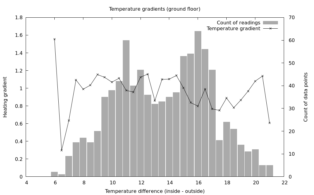
Was it worth it?  The graph above shows a visual representation after running the system with measurements being recorded over one winter.  The line is the temperature gradient at a particular temperature difference, and the bar shows how many readings went into that aggregate value (so you can see we can probably safely ignore the outermost data points as not having enough input data).  I think it’s not totally clear; the definitely does seem to be a downward trend in the heating rate as the temperature difference increases, but there’s also some upward spikes including at the highest temperature differences.  However, there are several confounding factors:

  1. The boiler temperature could have been changed as the outside temperature changed, which would affect the rate of heating but isn’t observable by this method.
  2. The downstairs temperature sensors is in the kitchen, so can be affected by cooking being done at the same time as the heating is on.  Again, this isn’t currently observable by the system, although real-time energy use data for the house is available so could potentially help here.
  3. Similarly, doors being open or closed can make a big difference, as can room occupancy.  These are awkward to measure and account for.

For comparison, here’s the same graph for the first floor, which isn’t affected by the “cooker effect”:

1f_gradients

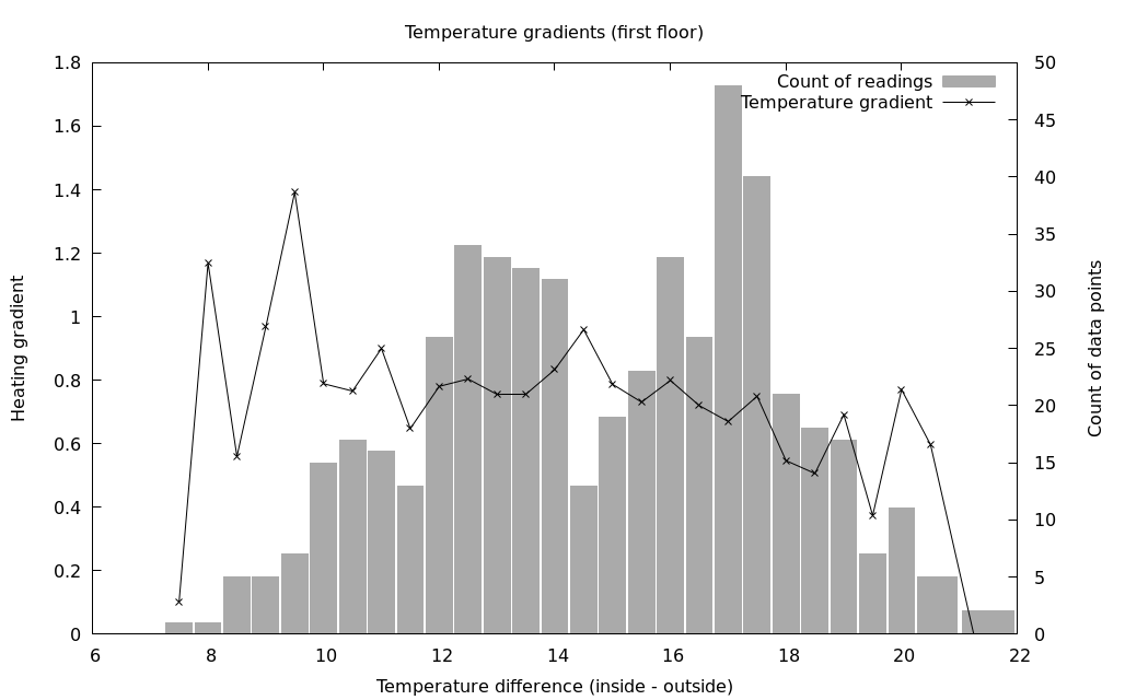
Although I knew it going into implementing this gradients API, a better (if more time consuming to implement) method would be to actually record the time-series data for temperature and boiler on/off over time.  This way, it would be possibly to try out different algorithms on historical data, and also the logic as to what data to record would be moved off the client.  Luckily this is also quite a neat UI feature too, so is appealing as a next step for development.

Cleaning up the API

As the REST API was starting to get a bit bigger and was basically undocumented, I was starting to find it difficult to keep it in my head and thought it was time to document it.  In doing so, I’ve started to move it over to flask-restplus, where one of the advantages is that it gets Swagger documentation and UI automatically.

Screenshot from 2019-10-06 22-27-04

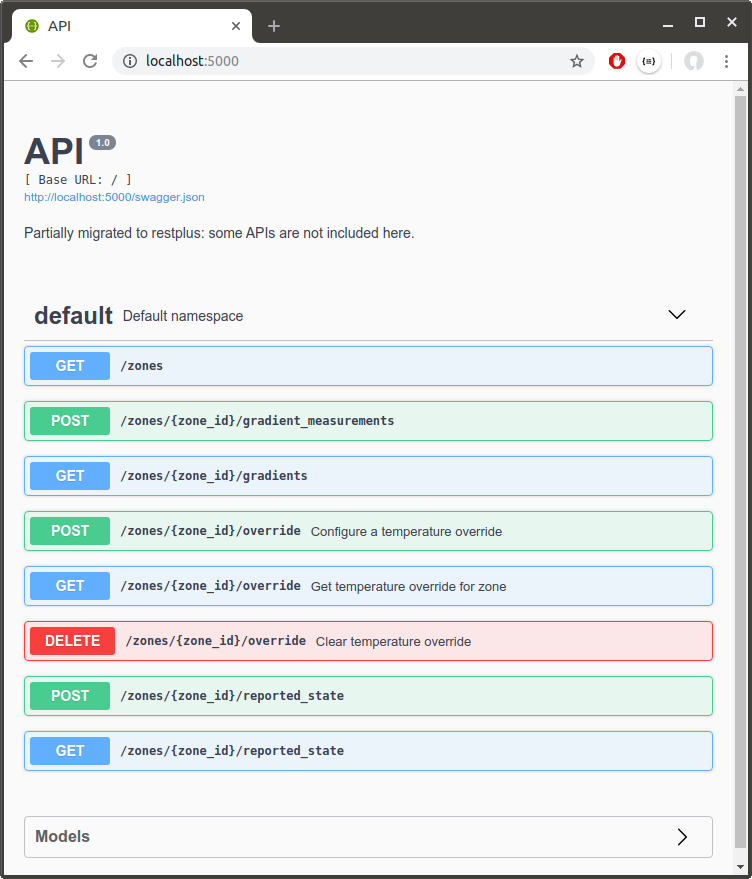
One of the annoying things about this is that it doesn’t work well when hosted on a proxy server not at the root.  There’s a few threads about this issue online but no pleasant solution that I’ve found: I don’t want to have to modify the application to know its actual root, and I don’t want to modify the proxy configuration to know the app uses Swagger ideally (maybe that’s the better option).  I think there’s still room for someone to figure out a good solution here.

There’s still work to do; I moved some of the zones APIs to flask-restplus and tried to clean them up along the way, but there are still improvements that could be made: e.g. the schedule API could be moved under zones since it lists out each zone separately anyway (and could probably do with some thought applying as to how to make it more RESTful and single-purpose — seeing target_override in there for example is somewhat cringe-worthy.

Conclusion

There’s still a lot of exciting avenues to explore: keeping a temperature history that can also be used to do machine learning for the temperature prediction, modifying the scheduler to start the heating early according to the prediction, integration with other home automation tools, and a lot more.  However, having used Boiler.io for two winters now, I’m really pleased with the stability and usability as it currently stands.  It’d also be great to enable other physical devices to work with it (e.g. some of the Z-Wave controllers), so if you have one of these and are interested in trying it please let me know.

Categories
Hacking Z-Wave

Getting Started with Z-Wave

emon_and_zwave
Left: MultiSensor 6 (Z-Wave), Right: EmonTH V2 (used in previous articles), Bottom: Z-Stick

Having recently acquired a couple of Aeotec MultiSensor 6 devices, I decided to investigate how to make them easy to use via MQTT so I could use them from BoilerIO (my IoT heating control) and EmonCMS (the energy/home monitoring system from OpenEnergyMonitor.org).

In this article I present the beginnings of a Z-Wave to MQTT bridge as well as discuss the basics of Z-Wave to help you get started with it.

If you want to get straight to the code, jump to the section on the MQTT bridge, check out the code on Github, or run pip install zwave-mqtt-bridge.

Z-Wave Concepts

A number of nodes (up to 256) can form a Z-Wave network.  The network can have one or more controllers, with at least one primary controller.  The primary controller has a Home ID that identifies the network, and assigns Node IDs to nodes as they join (are “included”) in the network.

Nodes have a product type that defines their behaviour.  The Z-Wave specification lists a number of command classes that are required and optional for particular product types; these command classes specify a set of commands (with parameters) that a device must implement.  For example, the “multilevel sensor” command class, number 0x31, defines a multilevel sensor report command, which is used by a device to advertise sensor readings.  It contains fields to indicate the scale, unit, and size of the data followed by the actual data itself.

Communication is asynchronous, and applications are generally built in an event-driven way as a result.  For example, sending a “Get” command to retrieve a sensor reading value may later result in a report command being sent back.  However, devices may be battery operated and not awake at the time readings or configuration changes are requested, so the application cannot simply wait for responses before continuing; the controller should deal with retransmission at the correct time for you.

“Association groups” allow nodes to communicate and send events to each other.  This is how, for example, a light switch and an associated bulb might be configured so that when the switch is pressed the bulb is notified and toggles its state.  Devices are required to have at least one notification group, the lifeline notification group, that includes the primary controller and is established when the device is included into the network.  The Z-Wave standard also imposes requirements on the commands sent to this association group, e.g. multilevel sensors are required to periodically send a report to the lifeline association group with their readings.

Hardware

montage
Unboxing the MultiSensor 6

The Aeon Labs Z-Stick and the Aeon Labs MultiSensor 6 are the two main devices used throughout this article.

The MultiSensor 6 provides temperature and various other sensor values over the Z-Wave network, and is powered either from USB or up to two CR123 batteries.  One interesting feature for future BoilerIO work is the motion and luminance sensors, which could be used to indicate presence.  Lower precision temperature reporting, relatively infrequent reporting when on battery, and proprietary firmware and hardware designs are downsides compared with the EmonTH I’ve been using so far.

The Z-Stick is s static controller that exposes a serial API (the “Zensys API”) for which there seems to be little public documentation (and the reply from the Z-Wave alliance to this post suggests that there is no intention to make this information public).  The OpenZWave project has reverse-engineered this protocol and has a list of supported controllers (of which the Aeotec Z-Stick is one).  If you are going to do a similar project then it’s worth checking the controller you plan to buy is on that list.

OpenZWave and python-openzwave

The OpenZWave project provides a way for developers to write applications that can interact with a Z-Wave network using a PC-based controller such as the Z-Stick mentioned above.  OpenZWave is written in C++, and so we are using python-openazwave which is a set of Python bindings to OpenZWave.  OpenZWave is used in some significant home automation projects such as openHAB and Domoticz to interface with Z-Wave devices.

Installing python-openzwave on the Raspberry Pi

Grab a copy of the python-openzwave repository from github:

$ git clone https://github.com/OpenZWave/python-openzwave

This checks out the master branch, which is ‘unsupported’ and in development, so you may want to switch to a release branch such as v0.3.3 and install dependencies, build, and install it like so:

$ sudo apt-get update && sudo apt-get install libudev-dev
$ cd python-openzwave
$ git checkout v0.3.3
$ git submodule update --init
$ make build
$ sudo make install

This can take quite some time on a Raspberry Pi since it involves downloading and building OpenZWave.

The Aeon Z Stick has a built in battery and can operate either as a standalone controller with a serial interface when it is plugged into your USB port, or in inclusion/exclusion mode when not plugged in.  Assuming the device is plugged in, you should get a serial port that you can use to communicate with it; on my system this is /dev/ttyACM0 but the number at the end may differ.

ozwsh.png
The [py_]ozwsh utility that comes with python-openzwave is useful for exploring and debugging your Z-Wave network.
Python-openzwave comes with a utility called the OpenZWave shell which is a somewhat quirky ncurses-style command-line utility that lets you perform actions on the network.  When installing python-openzwave using the method above, the XML configuration files that describe the devices might not be found by ozwsh so you can pass in their location on the command line.  To start the shell, run:

$ ozwsh -d/dev/ttyACM0 -c/usr/local/lib/python2.7/dist-packages/python_openzwave/ozw_config/

Some quirks to be aware of: You can use TAB to move between panes and therefore get access to scrolling on the main window.  You can’t cd to paths, only to “directories” in the current level.  The hierarchical layout that the tools presents makes sense but is an abstraction and doesn’t really represent how the Z-Wave network actually works.  The utility was renamed to py_ozwsh in version 0.4 and higher of python-openzwave.

Z-Wave Bridge to MQTT (and EmonCMS)

system-architecture.png

I wrote a simple Z-Wave to MQTT bridge that interfaces between Z-Wave and MQTT, and tested it with the MultiSensor 6 (with others coming in future).  The goal is to provide a simple and universal service that my (and others’) home automation can interact with.  Here are some steps to help you get started with it:

  1. Install python-openzwave as above.  Note that this is not available on PyPI so isn’t automatically installed via the pip command below.
  2. Install the Z-Wave MQTT bridge: you can install this via pip or from the repository on github; for example pip install zwave-mqtt-bridge.  (At the time of writing this depends on the boilerio package just for configuration file parsing but that should go away soon.)
  3. Create a configuration file, /etc/sensors/config, to specify your MQTT server and the base topic path to publish to.  See the README.md file for an example of a skeleton configuration file.
  4. Run the binary: $ zwave_mqtt_bridge.

Once you’ve done this, you can use the moquitto_sub tool to see the messages that are being published, for example:

$ mosquitto_sub -h (host) -u (username) -P (password) \
                -v -t emon_sensors/\#
emon_sensors/ZWaveNode6 {"temperature": 19.299999237060547}
emon_sensors/ZWaveNode6 {"humidity": 52.0}
emon_sensors/ZWaveNode6 {"luminance": 11.0}
emon_sensors/ZWaveNode6 {"ultraviolet": 0.0}
...

You can follow the instructions in the README to have the ZWave bridge start from systemd and run as an unprivileged user.

emoncms.png

To get this to work with EmonCMS, you need to post to EmonCMS when messages are published to the configured MQTT topics.  I wrote a simple Python script that you can find in my emonhub fork on github to do this, or you can use the PHP script provided with EmonCMS (though I had issues with it).

How it works: Using Z-Wave from a Python application

The examples that come with python-openzwave show how to initialise your connection to the Z-Wave network.  They use a ZWaveOptions object for configuration that exposes functionality from the C++ OpenZWave library: configuration is taken from a number of places including system-wide and per-user options files and the command line.  The application can tell OpenZWave the command line it was called with, and OpenZWave will then do common parsing of Z-Wave related options.  The application can also set options directly through the object, which is the approach I would suggest:

# Initialise openzwave.
zw_options = ZWaveOption(args.device, user_path=".")
zw_options.set_console_output(False)
zw_options.lock()
network = ZWaveNetwork(zw_options)
network.start()

while network.state != network.STATE_READY:
    time.sleep(1)


Getting sensor readings from the MultiSensor

There are three ways that sensor readings can be obtained from the MultiSensor: via a GET command that specifically requests the value of a sensor, via the reports that the device automatically generates at specified intervals, and similarly via reports generated when sensors crosss thresholds.  The latter two options are the best since we don’t want to constantly be requesting reports from the device.

Receiving sensor reports

Python-openzwave uses the louie framework for signalling events within Python.  I couldn’t find huge amounts of documentation about this at the time of writing, but it is based on PyDispatch and, for the purposes of receiving events, is pretty simple to use.  There is a connect method in the louie.dispatcher module that allows you to connect a Python callable up to a signal indicated by a hashable Python object.  By subscribing to the SIGNAL_VALUE signal, your application will be notified when sensor reports are received.

Code similar to the following would connect the listener and print a message with information about what was received whenever an event occurred:

import signal
from louie import dispatcher
from openzwave.network import ZWaveNetwork
from datetime import datetime

# ... network setup code here ...

exit = False
def sigint_handler(signal, frame):
    global exit
    exit = True
signal.signal(signal.SIGINT, sigint_handler)

# Connect to events
def value_updated(network, node, value):
    now = datetime.now().isoformat()
    print "%s: Value updated node_id: <%d>, label <%s> new value <%s> instance %d" % ( now, node.node_id, value.label, str(value.data), value.instance) 
dispatcher.connect(value_updated, ZWaveNetwork.SIGNAL_VALUE)

# Loop until we're told to exit:
print "Running: Ctrl+C to exit."
while not exit:
    signal.pause()
dispatcher.disconnect(value_updated, ZWaveNetwork.SIGNAL_VALUE)

One thing to watch out for here is that exceptions are swallowed in the signal handler, so if you get an exception it appears as though your function didn’t complete.  As such, it’s worth wrapping the code in your signal handler with try/except.

Values

Python-openzwave stores values (as instances of ZWaveValue) with devices; these are created depending on the command classes and specific configuration information for each device type.  They are initialised with default values and when reading them directly they may be out of date or wrong.

This excerpt from the zw100.xml file for the MultiSensor 6 shows a value, the Group 1 reporting interval, being defined with a default of 3600:

...
        type="int" index="111" genre="config"
               label="Group 1 Interval" units="seconds" 
               min="1" max="2678400" value="3600">
...

The value="3600" causes the ZWaveValue instance to be initialised with the value of 3600 so if you need to get the actual value being used by the device, you first need to call its refresh method.  Your application will then receive a SIGNAL_VALUE notification with the data.

You can also check the is_set property of the ZWaveValue instance to determine whether the value was actually set as a result of a report from the device or it is just the default specified in the config file.

To set the value, simply set its data property to the desired value.

Configuring report interval and type

As part of the configuration command class, the contents and frequency of up to three sets of automatically generated reports can be configured.  These are documented in the firmware manual.  The relevant configuration parameters are 101-103 for the desired contents of the report (as a bitfield whose values are defined in the firmware spec) and 111-113 for the interval in seconds for group 1 through 3 respectively.  When a reporting group’s interval occurs, the MultiSensor sends a report for each parameter requested in the corresponding configuration value.

Note that, when on battery, the MultiSensor cannot send reports at an interval shorter than the wake-up interval, and the minimum wake-up interval is 240 seconds.  (This is possibly a problem for use with BoilerIO, but when connected to USB this limitation does not exist.)

As part of our application we want to configure the wake-up and reporting interval appropriately: here is some example code to do that:

# Find wake-up and reporting interval and set to desired value:                                     
for value in network.nodes[node_id].get_values().values():                    
    if value.label == "Wake-up Interval":
        value.data = 240
    if value.label == "Group 1 Interval":                               
        value.data = 240

Integration issues

Battery operation with the MultiSensor

When testing the MultiSensor on battery, I noticed an issue that configuration updates weren’t happening when the device was woken up.  Looking at the log files, I saw sections like this:

2017-11-11 18:52:52.245 Info, Node006, Received reply to FUNC_ID_ZW_GET_NODE_PROTOCOL_INFO
2017-11-11 18:52:52.245 Info, Node006,   Protocol Info for Node 6:
2017-11-11 18:52:52.245 Info, Node006,     Listening     = true
2017-11-11 18:52:52.245 Info, Node006,     Beaming       = true
2017-11-11 18:52:52.245 Info, Node006,     Routing       = true
2017-11-11 18:52:52.245 Info, Node006,     Max Baud Rate = 40000
2017-11-11 18:52:52.245 Info, Node006,     Version       = 4
2017-11-11 18:52:52.245 Info, Node006,     Security      = false

This indicated that the controller thought the device was a listening device, which is not the case when it is battery-operated, resulting in some features not working correctly.  I suspected that this configuration came from the controller because this set of messages was appearing quickly on initialisation, which I confirmed by connecting to the network with the MultiSensor powered down.

To address the issue, I excluded then re-included the device when it was on batteries and it now worked correctly.  These are the new, correct, log messages:

2017-11-11 18:52:52.267 Info, Node007, Received reply to FUNC_ID_ZW_GET_NODE_PROTOCOL_INFO
2017-11-11 18:52:52.267 Info, Node007,   Protocol Info for Node 7:
2017-11-11 18:52:52.267 Info, Node007,     Listening     = false
2017-11-11 18:52:52.267 Info, Node007,     Frequent      = false
2017-11-11 18:52:52.267 Info, Node007,     Beaming       = true
2017-11-11 18:52:52.267 Info, Node007,     Routing       = true
2017-11-11 18:52:52.267 Info, Node007,     Max Baud Rate = 40000
2017-11-11 18:52:52.267 Info, Node007,     Version       = 4
2017-11-11 18:52:52.267 Info, Node007,     Security      = false

Device name changes

The Aeon Z-Stick is designed to work as a static controller when plugged into a host PC, but in order to include and exclude device it is necessary to unplug the device from the PC, move it near to the device being included/excluded and press the button.  However, unplugging the device will stop the Z-Wave network connection from working and there is nothing in place to restart it when the device is reconnected.  Further, the device is not guaranteed to re-appear with the same device name it originally had, and certainly seems not to if file handles to the original device are kept open.

The Z-Stick appears as a modem device, but other devices may also appear as modem devices (ttyACM*).  The particular Z-Stick can be identified by it’s Home ID, but to query this you have to first determine that a given device is in fact a Z-Stick and connect to it.

I don’t think there are any great solutions to this: some options are:

  • Watch for the device node disappearing and disconnecting from the network if it does.  This closes any open file handles and, if the device was the only ACM device on the system then it will be more like to re-appear as the same device again (/dev/ttyACM0).  Not ideal because replugging the device might unintentionally stop the application from working without the user knowing.
  • Connect to any ACM device that is attached if the one we were using was disconnected, or connect to all Z-Sticks attached.  Better, but required indirection of ZWaveNetwork objects because the device name is configured in the ZWaveOptions object that is created, locked, and passed to the network object at initialisation time.

The zwave-mqtt-bridge currently implements a solution using the watchdog Python module that gives you callbacks when directory contents change (i.e. files are created or deleted).  On Linux, this uses the INotify API that is provided by Linux 2.6+.

Conclusion

This article has hopefully helped you to interface with Z-Wave devices, as well as provided an introduction to some of the intricacies of using Z-Wave from Python.

In future we’ll look at integrating the MultiSensor 6 and other Z-Wave devices with BoilerIO in more depth.

Useful reference material

Categories
Energy

Power Usage of Virgin TiVo, V6 TV box, and SuperHub

IMG_2468

Modern devices such as TVs tend to be able to run in standby mode quite efficiently, which means the common advice about turning them off completely is becoming less relevant.  However, retaining the overall aim of reducing your overall energy footprint, new always-on devices such as modems, routers, set top-boxes that have a recording facility, etc., are more relevant targets as they are still active even when you’re not using them directly.

At home we use Virgin Media for our broadband and TV, with a TiVo box for recording.  Having just upgraded to the SuperHub 3 and V6 TV box, I was curious to see if the power consumption of these always-on devices had improved.

Results

power_final

TV equipment

It looks good: the V6 box uses just over a third of the energy that the TiVo uses over a day of operation.

To get to the “one-third” estimate quoted above, I used a couple of observations and modelled the usage of the device over a typical day – your mileage may vary.  As I will note below, the original Virgin TiVo seems to have two modes of standby and also seemed to be awake when it was not recording and in standby when I went to observe it on one occasion.  I’m not sure exactly when this happens/what the cause is, nor am I sure the rules governing the higher-power standby, so I’ve tried to account for these by including 1 hour of time in the higher-power standby.

Virgin TiVo Virgin V6
  Duration Power Energy/day Power Energy/day
Standby 1 16h 11W 176Wh 3W 48Wh
Standby 2 1h 13W 13Wh 3W 3Wh
Recording 4h 15W 60Wh 10W 40Wh
Watching 3h 19W 57Wh 10W 30Wh
Total 24h 306Wh 121Wh

Superhub (v1 vs. v3)

This is less good.  I use the Superhub in modem mode (i.e. no wifi or other features enabled since these are implemented elsewhere on my network), but we see a modest 1W increase in general power usage (10W for the SH1 vs. 11W for the SH3, consistently):

SuperHub 1 SuperHub 3
  Power Energy/day Power Energy/day
Modem mode 10W 240Wh 11W 264Wh

The (quite unscientific) measurement method

IMG_2464

I used a plug-in power meter to measure the power consumption. This power meter is a modern equivalent, though the one I had is this one that is no longer sold.

The meter has a function that totals energy use but the resolution of the reading is too low for this testing, so instead I set up a camera pointing at the meter and sampled the reading at the start of each minute.  I then took the average (mode) for the period as the result.

This could obviously be done much more efficiently and accurately with a meter that supports a data-logging facility and has higher accuracy, but I didn’t have that at the time and this served my purpose.

An aside on video tools

I used a Raspberry Pi Zero W with a camera module (without the IR filter, just because that’s what I already had lying around) to record video of the power meter during the measurement period.  I used the raspivid program to capture video.  To keep file sizes down, I saved the video at 320×240 resolution using a command similar to the following:

pi@cam:~ $ raspivid -w 320 -h 240 -o 2_v6_recording_standby.h264 -t $((1000 * 60 * 45))

$((1000 * 60 * 45)) in this case computes to 45 minutes of time, since the -t option specifies how long to record for in milliseconds.  This creates a raw h264 file, but it needs to wrapped in a container format in order for media players to understand it: you can use the MP4Box program to create this (part of the gpac package):

pi@cam:~ $ MP4Box -add 2_v6_recording_standby.h264 2_v6_recording_standby.mp4

I then used a processing script to extract the image at 1-minute intervals, similar to the following (run on a different machine that had a working ffmpeg command):

#!/bin/bash

for i in `seq 0 $((2 * 60))` ; do
    ffmpeg -ss $(($i * 60)) -i v6_recording.mp4 -frames:v 1 $i.bmp
done

Observations

Virgin Tivo box

Firstly: standby.  There are multiple power-saving settings for this device: the box was set to ‘Sleep’ for these tests, which is supposedly the most aggressive power-saving mode (see the Virgin Media help page on the subject for more info).

Here is a graph showing the unit in standby with a recording finishing at minute 51 and the subsequent time spent idle:

data.png

Note that for some time after the unit enters standby it sits at 12W, then later appears to power back up and then drops to 11W.  I assume this is indicative that it enters a deeper sleep state when using 11W.

When I came to do further testing the next day, having left the power meter plugged in, I noticed it was showing 13W-15W for a while, then it reverted to 11W.  It wasn’t turned on or recording at the time, so I assume it was doing some scheduled activity.  As a result of this and the higher power draw when initially entering standby, I modelled a second standby state for the device above but it is a complete guess as to how much time is split between the states.

Watching TV consumes a relatively constant 19W:

data.png

Virgin V6 box

The V6 box was relatively consistent in its power usage compared with the original Tivo.  Again, it was set to the most aggressive power-saving mode, the Eco standby mode.

Here is the unit in standby and idle:

data.png

And watching TV – an almost-constant 10W:

data.png

Finally, recording a program while the unit was in standby mode:

data.png

Conclusion

To put the 161Wh/day saving across both appliances into perspective, for me it accounts for a reduction of around 5% of my always-on energy consumption at home.  I’d say it’s neither totally insignificant nor huge.  However, I hope that by having information like this available to consumers it can enable people to take it into account when making purchasing decisions, and I couldn’t find anything to this level of detail already published for these two devices.

Tools like OpenEnergyMonitor or a smart meter can help you to understand your energy usage better, and with the help of these you could consider performing an audit to reduce unnecessary sources of consumption.

Categories
Boiler control Hacking

Controlling your heating from anywhere

IMG_2272

Previously we discussed the algorithms that can be used to control a domestic heating system, built a simple UI to schedule the temperature changes, and reverse-engineered a pre-existing RF relay to control the boiler.  So far the web service that provides the UI has been deployed on a PC at home but, since you’re most likely to want to override your heating controls when you’re unexpectedly arriving home early or late, we need a site that can be reached from anywhere.

This article describes changes to the software that were necessary to achieve that, some discussion about the technical choices, and step-by-step instructions to set this up for yourself.  If you’re here just for the step-by-step setup guide, jump to “Deploying BoilerIO on AWS”.

As usual, all source code is available under an MIT license on github.

Client, server, and device

In the previous article, we assumed that the hosts running the web service and issuing boiler control commands were on the same network and, in fact, probably the same host.  To put BoilerIO online (i.e. provide access to controls from anywhere), this assumption is no longer true.  Although you could contemplate putting the web-server host into the DMZ (i.e. exposing it to the Internet whilst retaining a connection to your network), this is a massive can of security worms and is not suggested.  You could consider hosting your own server on a completely separate network if you have access to multiple public IP addresses, but this is not the common case and so is not discussed here.

system-architecture-3.png
Updated BoilerIO architecture

So now, we have three distinct applications:

  1. Clients: Your phone or PC, hosting the scheduler application in a web browser and accessing and controlling heating controls provided by the service.  This is a JavaScript/HTML web-app currently (though you could imagine other client apps such as an iOS app).
  2. The service: This provides the backend that everything else talks to: it stores schedule data, cached temperatures, and hosts the static files needed for the web UI.  It could be run across several servers with a load balancer, but for a domestic installation a single, low-power VM is sufficient to host everything (the backend uWSGI app, the frontend web-server, and the Postgres database).
  3. Devices: This is just a special case of a client.  Currently there’s no real difference in how they access the service, other than making use of additional HTTP endpoints to update the cached temperature on the server, etc.  They execute the state the user has programmed via the web interface by interacting with the local infrastructure (e.g. issuing boiler commands).  They are fixed ‘appliances’ running on the user’s local network and currently authenticate the same way as user-facing clients, using a shared secret.

In future, role-based access control could be used to restrict access to endpoints on the backend service depending on whether a device or user credential was used for authenciation.

Security considerations

With any online service there are always security risks and the possibility of unknown methods of attack exists.  One future piece of work is to write a threat model for BoilerIO.  In the meantime, some key considerations include:

  1. Ensuring that the backend service requires authentication as a user or device for any API access.  See below for more info: this is currently achieved using HTTP Basic Authentication (over HTTPS), as supported by nginx.
  2. Ensuring that communication with the backend service is always encrypted.  Again, this is implemented server-side: the web-server configuration redirects HTTP requests to the HTTPS protocol.  The device code supports but currently doesn’t require HTTPS as this is not convenient for local-only deployments.
  3. Ensuring that the device doesn’t allow unverified certificates, to reduce the likelihood of man-in-the-middle attacks.  This is the default for the device code and, for the UI, browsers should provide an indication if the certificate is bad.
  4. Sanitising inputs to try to filter out anything that might cause damage (either malformed or otherwise malicious input).
  5. Running all services with least privilege.  All device code and service code should run as an unprivileged system user.  Further improvements could be made by creating either SELinux or AppArmour policies for the modules.
  6. Not exposing anything unnecessary externally such as the database or any service on the device itself.  The device now only makes outbound connections, and only requires HTTPS access to the scheduler service.
  7. Use of strong passwords, since you are in control of the entire deployment and can use utilities in your browser to store passwords, you can have separate secure passwords for each user and device that is accessing the service.

The backend service

Authentication of users and devices making API requests to the backend service ensures that only you and the devices you own can read and configure the heating schedule and state.

There are many ways of implementing authentication, either through the application itself or the web-server hosting it.  Since BoilerIO doesn’t yet support authentication itself (e.g. via OAuth), an expedient way to achieve a reasonable level of security is to configure the web server to require HTTP authentication.  Since I’m using nginx, I’m forced to stick with HTTP Basic Auth since their Digest Auth implementation is incomplete at the time of writing.  It’s critical the authentication is done over a secure (HTTPS) connection to prevent credentials being stolen by capturing the authentication traffic.

Note that using Basic Auth means that, if someone acquires the HTTP requests in cleartext, the password will be directly available to the intruder.  Although interception shouldn’t normally happen with TLS, you may, for example, be subject to man-in-the-middle attacks if you have rogue certificates installed on your system (so that your site looks legitimate to the browser but is being impersonated).  This is sometimes the case on corporate systems employing SSL proxies.

For good overall security it is best to use long, random, machine-generated passwords to access your site.  You can configure modern browsers to remember those passwords on computers you trust, and if you forget or lose them you can easily reset them.

The device(s)

The scheduler operates on the user’s local network to interface with temperature sensors and the boiler controller (any of which may be running on the same host) and uses the scheduler web service to get an up-to-date heating schedule.

Assuming that the “device software” is hosted on a private network, and not reachable from the Internet, then the main security considerations are:

  1. Protecting against invalid responses from the scheduler service, in case that has been compromised.  The code as-is does do some validation of responses and will ignore faulty responses.
  2. Ensuring any parts of the local configuration, such as the MQTT broker, are sufficiently locked-down.  This is up to the end user to configure.

Deploying BoilerIO on Amazon Web Services

Amazon Web Services (AWS) provides a cheap and convenient way of getting server resources with a public IP address.  You may have access to alternatives including your own server, in which case the AWS-specific parts can be ignored or modified to suit your environment.

BoilerIO currently uses a Postgres database as a backend, so it’s most convenient to configure our own services on a VM.  Elastic Beanstalk can provide a Python environment but then there’s still the database to be hosted and Amazon charge for the underlying EC2 instance anyway.  I chose to use a Lightsail VM.  Lightsail is essentially a simpler version of EC2, made to look more like a traditional VM hosting service with simple pricing and configuration.

For any of this to be useful, you need to have the pre-requisites including a temperature sensor (such as the EmonTH) with a compatible interface (for EmonTH, you can use the JSON mode I added to emonhub) between it and MQTT, and a way of interfacing with your boiler (such as the Danfoss RF interface running on a JeeLink v3c 433MHz, if you have a compatible Danfoss receiver).

Setting up the device side is a little complex as you need to get the above parts working together.  More documentation will be added over time, as well as more complete coverage for other types of boiler setup and temperature sensor.  For now, if you are technically-savvy and have the requisite hardware then you can set this up for yourself and use these instructions to configure the server side.

Step 1: Create your VM

Instance-types.png
An Ubuntu 16.04 instance of the cheapest type should be sufficient for this application.

You need to have signed up for AWS.  Once you have an AWS account, you can get to Lightsail from the AWS Management Console to configure both an ‘instance’ (a virtual machine), and a public IP address.

The instructions here assume an Ubuntu 16.04 LTS image,.  A simple 512MB/1 VCPU/20GB SSD instance should be sufficient for this application, and is currently priced at $5/month.

You’ll need to configure a way to ssh into the VM.  You can either use the web console, or connect in using either an existing ssh key or one that you generate.  I prefer to generate a key locally and upload just the public key part.  On Windows, you could use the PuTTY, or on Mac OS you can just use openssh directly from the terminal.  All commands below are run on the server unless noted otherwise.

Step 2: Check out the BoilerIO code

The BoilerIO code is hosted on github; you can easily grab a copy:

$ git clone https://github.com/adpeace/boilerio.git

Step 3: Database configuration

The web backend for BoilerIO requires a Postgres database to be configured:

Firstly, install postgres:

$ sudo apt-get install postgresql

Then, we need to create a user for the backend.  I would suggest using a long, random, password for this user, which you can generate using the pwgen utility.  Once you have a password, create the user and database for the scheduler:

$ sudo -u postgres createuser -P scheduler
Enter password for new role: 
Enter it again: 
$ sudo -u postgres createdb scheduler

Then, create the tables etc. using the script in the boilerio repository:

$ sudo -u postgres psql scheduler <boilerio/scheduler.sql
[sudo] password for ubuntu: 
SET
SET
...

Step 4: Installing the app

This is a simple case of installing the Python package:

$ sudo apt-get install python-setuptools
$ sudo easy_install pip
$ cd boilerio
$ sudo -H pip install .

The package also relies on a config file, /etc/sensors/config, as described in the README.md in the repository.  Only the configuration options relevant to the web app are neede since we aren’t installing the other components on the server.  A sample configuration file might look like this:

[heating]
scheduler_db_host = localhost
scheduler_db_name = scheduler
scheduler_db_user = scheduler
scheduler_db_password = 

Step 5: Configuring uWSGI

uWSGI a web server that can be used to serve the BoilerIO flask app behind nginx.  We use this because it is more performant, robust, and secure that the built-in werkzeug web-server provided as part of flask (which is only intended for development use).  To install it, run the following:

$ sudo apt-get install uwsgi uwsgi-plugin-python

It’s best to run uwsgi apps as an unprivileged user, so we need to create the user and then set permissions of various locations appropriately

$ sudo adduser --no-create-home --system boilerio

Now, create a configuration for the app.  Create the file /etc/uwsgi/apps-available/thermostat.ini:

[uwsgi]
socket = /var/www/boilerio/thermostat.sock
module = boilerio.schedulerweb:app
uid = boilerio
gid = www-data
chmod-socket = 664

Finally, create the directory for the socket, enable the app, and restart uWSGI:

$ sudo mkdir -p /var/www/boilerio
$ sudo chown boilerio:root /var/www/boilerio
$ sudo ln -s ../apps-available/thermostat.ini /etc/uwsgi/apps-enabled/
$ sudo systemctl restart uwsgi

You can check that it is running by checking the output of ps:

$ pgrep -a uwsgi
18503 /usr/bin/uwsgi --ini /usr/share/uwsgi/conf/default.ini --ini /etc/uwsgi/apps-enabled/thermostat.ini --daemonize /var/log/uwsgi/app/thermostat.log
18511 /usr/bin/uwsgi --ini /usr/share/uwsgi/conf/default.ini --ini /etc/uwsgi/apps-enabled/thermostat.ini --daemonize /var/log/uwsgi/app/thermostat.log
18512 /usr/bin/uwsgi --ini /usr/share/uwsgi/conf/default.ini --ini /etc/uwsgi/apps-enabled/thermostat.ini --daemonize /var/log/uwsgi/app/thermostat.log

To ensure uWSGI starts at systems startup, check that the RUN_AT_STARTUP variable is set to yes in the /etc/default/uwsgi file.

Step 6: Configuring nginx and HTTPS

To install nginx, simply run:

$ sudo apt-get install nginx apache2-utils

Step 6a: Let’s Encrypt!

lightsail-firewall
Enabling HTTPS through Lightsail’s firewall

To set up HTTPS, you can use the Let’s Encrypt! Certificate Authority to get a certificate for your HTTPS server that will be trusted by most browsers.  Let’s Ecnrypt! provides domain-validated certificates, which are probably good enough for your needs.  In order to get the certificate, you have to prove (with the help of a tool called certbot) that you are in control of the domain.  This gives you a way of setting up secure communication to your site, but it does not prove to users that you are who you say you are beyond the fact you are the current owner of the domain.

To set up HTTPS using a Let’s Encrypt! certificate, you can follow the certbot instructions.

On AWS Lightsail, there is a firewall protecting your VM that you will need to reconfigure to allow HTTPS (port 443) incoming connections before configuring certbot.

Step 6b: Basic authentication setup

To use HTTP Basic Authentication, you need to setup a htpasswd file with usernames and hashed passwords.  This shouldn’t be served over HTTP; it can be kept in /etc/nginx well out of the way of the HTTP server.  The easiest way to create it is using the htpasswd utility.  Since there isn’t a native nginx utility for this you can use the one from the apache2-utils package.   You can install this, then create users for your site, using the -c option the first time around to create the non-existent file.  We’re using sudo just to get write permission on /etc/nginx here:

$ sudo htpasswd -c /etc/nginx/thermostat_htpasswd 

$ sudo htpasswd /etc/nginx/thermostat_htpasswd 

It is recommended to use long random passwords here; you could generate these with pwgen(1), and then use your browser to remember the password.  You’ll need to include the scheduler password in the /etc/sensors/config file on the host running the scheduler itself: for more info see the README.md in the repository, especially the section on the configuration fie.

Step 6c: nginx configuration file

Finally, you need to set up your configuration to serve the BoilerIO API and the static pages for the user interface.  To do this, create a new configuration file that looks something like this under /etc/nginx/sites-available/boiler, then link it under sites-enabled and remove the default site:

server {
    listen 80;
    listen [::]:80;
    server_name ;
    return 301 https://$host$request_uri;
}

server {
    listen 443 ssl; # managed by Certbot
    ssl_certificate /etc/letsencrypt/live//fullchain.pem; # managed by Certbot
    ssl_certificate_key /etc/letsencrypt/live//privkey.pem; # managed by Certbot
    include /etc/letsencrypt/options-ssl-nginx.conf; # managed by Certbot

    root /var/www/html;
    index index.html;
    location / {
        auth_basic 'thermostat';
        auth_basic_user_file '/etc/nginx/thermostat_htpasswd';
        location /api {
            try_files $uri @boilerio;
        }
    }
    location @boilerio {
        include uwsgi_params;
        rewrite ^/api/(.*)$ /$1 break;
        uwsgi_pass unix:/var/www/boilerio/thermostat.sock;
    }
}

The config file above uses a different structure than that installed by certbot to redirect users from the HTTP site to the HTTPS site.  The certbot version does work, but the above avoids the if statement (see If Is Evil) and doesn’t include any of the statements that would cause any content to be delivered within the non-SSL server block, reducing the chance of mistakes in future changes to the configuration file.

It is important that the 301 Moved Permanently response happens before the authentication.  The sequence for a redirected request should be as illustrated here:

http-redirect.png

You can check that the flow is happening as you expect using a tool such as tcpdump or wireshark.  If you run tcpdump -w packets -i eth0 or similar on the server, access the site from your browser, then open the packet trace created in Wireshark, and filter on http you should see the following – note no authentication requests are shown:

wireshark.png
Wireshark trace showing no authentication is happening over HTTP

You can either modify the above configuration to serve the static files from elsewhere, or copy them into /var/www/html directory.

Conclusion

Setting up the service is currently not a simple operation but hopefully this article describes the process well enough to get a technically-savvy user started.

There is lots of further work to be done but, now we have the foundations set up, future articles can look at adding features such as sub-zone control and new types of sensor and actuator.  Watch this space, and please comment with anything you’d be interested in seeing.

Categories
Boiler control Hacking

The BoilerIO Software Thermostat

It’s time to step up from command-line control of the heating system I’ve been working on to having a weekly schedule and temporary override function available through a UI, making the system practical on a day-to-day basis.

As always, code described here is available on github under an MIT license.

Overview

The scheduler chooses a target heating temperature throughout the day and needs to be usable by someone non-technical to show the state of the system, provide a means to enter and edit a schedule, and provide a means to change the target temperature for a fixed period of time.

system-overview

To achieve this a new daemon and web service have been added to the architecture.  Here is a summary of the responsibilities of those components:

  • The Scheduler reads the weekly schedule from the database, and sends commands to the Boiler Controller to change the target temperature at the appropriate times.
  • The SchedulerWeb REST service provides a REST API over HTTP to get a summary of system status, set or clear the temperature target override, and add and remove entries from the weekly schedule.  This is implemented using Flask in Python, with uWSGI and nginx to provide a robust service.
  • The scheduler configuration database is a PostegreSQL database holding the schedule, a cached copy of the current temperature, and the target override configuration.  It’s the primary store for this information: the REST service updates it and the scheduler uses it to control the temperature.
  • The SchedulerWeb web frontend is an HTML5/CSS3/Javascript single-page web UI that makes use of the REST service to interface with the system from the user’s web browser.

Experience and implementation notes

Rather than trying to document the entire implementation, I will instead talk about each area and some of the challenges or points of interest, and the major decisions that were taken and why.  My day job is a lot lower in the software stack than this, so there may better approaches than what I’m presenting.

The HTML frontend

alignment
1px alignment issue (red line illustrates the problem) without left padding on input boxes

The app is designed to largely follow Google’s Material Design guidelines; I hadn’t realised when I started that there are stylesheets provided by Google that can be used so I implemented the styles I needed myself.

Since the fashionable choice of web-framework seems to change frequently I was initially resistant to using anything at all fancy, and instead use traditional jQuery directly.  In retrospect, not having some of the features of a slightly higher-level framework probably made the code worse that it ought to be and in future I might look at whether a framework provides a better frontend implementation.

Modern web development has definitely come on a long way since I last attempted it: the developer tools inside Chrome are great, though there are still cross-browser issues even when only supporting latest-generation browsers (for example implementing modal dialogs is still done manually even though there’s the dialog tag now, and I had issues with alignment and appearance of certain input fields).

The REST service

The backend service uses Flask, a neat framework for web apps in Python.

When developing your service you should be aware that werkzeug, the built-in web server, is not suitable for production due to security and scalability issues.  However, if you do use it during test you’ll find it also makes it easy to accidentally keep global state within your app, which you shouldn’t be doing because it won’t work when you’re inside a production server.  For that reason, I suggest starting to use uWSGI relatively early in your development.  It’s not difficult to use for test.

I’ll come onto a step-by-step deployment guide in an upcoming post, but I recommend that the web service be deployed using uWSGI behind nginx or Apache to get a secure and scalable deployment.  However, on Raspbian at least there are a couple of pitfalls I found with uWSGI: I used pip to install a relatively modern version.  The installation used a PREFIX of /usr/local.  For some reason, even with /usr/local/bin on my PATH, uwsgi did not work correctly unless called with its full path (despite printing a message stating the full path it had detected, which was correct).  Perhaps this is a security measure, but the failure mode here and on other issues I experienced was somewhat opaque and better error messages would have been useful.

To use uwsgi in production, it is helpful to have it start to host relevant services on system boot.  On Raspbian, this requires a systemd unit to be created (on other systems an init script, upstart job, or just adding to rc.local would be needed).  That nothing was already in place could be a result of the way I installed uwsgi, but in any case I followed the Debian package’s convention of creating a configuration file in /etc/uwsgi/apps-available and linking to it in /etc/uwsgi/apps-enabled.  The config I used was this:

[uwsgi]
chdir = /var/www/app/boilerio
socket = /var/www/app/thermostat.sock
module = schedulerweb:app
logto = /var/log/uwsgi/thermostat.log
uid = boilerio
gid = www-data
chmod-socket = 664

Note here that, for better isolation, I’m using a system user specifically for this service, and sharing a group with the web-server so I can create the socket with permisions for both to be able to access.

nginx and the URL namespace

The web service natively places its REST endpoints at root level.  As I use nginx to also serve static content – the client HTML/JS/CSS files – I decided to map the service under /api.  Files for the web client get served from /, and they make API calls assuming the api prefix .  I use a simple nginx configuration file to achieve this:

server {
    listen      80;
    server_name hub;
    charset     utf-8;
    location / {
        root /var/www/app/boilerio/static;
    }
    location /api {
        try_files $uri @boilerio;
    }
    location @boilerio {
        include uwsgi_params;
        rewrite ^/api/(.*)$ /$1 break;
        uwsgi_pass unix:/var/www/app/thermostat.sock;
    }
}

The endpoints and the data they expect are currently hand-coded in the Python web application code, which is less than ideal.  Defining a clear API where constraints on input and validation can be consistently and mechanistically verified is a better approach and an area for improvement.  Swagger seems like one good option to implement this, has integration options with Flask, and has the side benefit of a nice web UI for making REST calls to the service too.

The scheduler

After modifying the maintaintemp script to listen for new target temperatures over MQTT rather than having a static target passed on the command-line, the scheduler is able to periodically update the target temperature.  The current, simple, implementation polls the database once per minute, or when a trigger message is received, to load the currently-active schedule and target override.  It then selects a target based on these inputs and sends a message to the boiler controller to update the target temperature.  At startup, and when the controller for a zone restarts, the target request is sent immediately to avoid having to wait a whole polling interval.

This is a likely area for innovation in future: enhancing how the target is chosen using additional inputs or policies, enabling features like pre-heating to reach an upcoming set-point, altering the target based on presence information, and intelligently dealing with installations with multiple zones or independent controls within a zone.

The database

A PostgreSQL database is used to store the schedule and configuration.  This might seem like overkill, but when developing a web app where multiple processes need read/write access to the data it seems sensible to use a tool that is designed for that kind of environment, even if the scale it is being deployed at is relatively tiny, for a few reasons:

  • It avoids designing scalability out now.  If we used another approach that was “simpler” but couldn’t be scaled if necessary it would be a potentially large undertaking to fix.
  • You get a lot of correctness for free.  If, for example, the schedule were stored in a plain text file (say, as JSON), then it is definitely possible to make everything atomic.  But the hassle of getting it exactly right does not seem worthwhile when the database can deal with it all more efficiently from the beginning.

Another approach would be to use a document store like MongoDB.  There are pros and cons to either way (this strongly-worded post is an interesting read concerning problems faced in a practical application), but I decided to go with something I was familiar and confident with.  While having a fixed schema seems to be considered by some to be “overhead” or to slow down development, it can also reduce problems by helping to identify programming or design errors earlier in the cycle and certainly did not seem to make development difficult.

What about AWS/PaaS/Serverless?

A somewhat different approach could be to use Amazon or Azure web services.  Amazon have several relevant offerings here (and I believe Microsoft have alternatives too):

  • AWS IoT: This is a service that maintains a ‘shadow device state’.  User agents can post new ‘desired state’ and devices can post the actual state of the device.  AWS publishes messages to indicate various conditions including when the target and current state are divergent so that the device can change its physical state to match the desired state.
  • AWS Lamda and API gateway: This provides a potentially simple way to implement the scheduler REST API without having to host the web service component yourself, potentially reducing the maintenance burden.  You can easily provide authenticated access regardless of where you are connecting from.  Zappa is a tool that lets you easily run a Flask applications within Lambda, so could be used to allow the BoilerIO code base to be used without modification.
  • S3 could host the static files, such as the CSS, JS, HTML, etc. for the client app.
  • AWS DynamoDB or Relational DB services.  The latter could be a drop-in replacement as it has PostgreSQL support, whereas changes to the app (relatively minor/contained within one module) would be required for DynamoDB although that option does have more attractive pricing

The first issue to consider with this approach is what the connectivity requirements are and what is the user’s expectation of behaviour when their Internet connection is unavailable.  In this case, the minimum requirements seem to be that (i) the schedule should continue to run without interruption regardless of Internet downtime, and (ii) the user should be able to supply at least an override even if the schedule is not editable.  Both are doable, the first trivially since the scheduler can (and should) be run locally to the installation.

The second issue is vendor lock-in.  These services are proprietary, and there’s no way to run local versions of them either for testing or deployments where using an online service is suitable.

In the end I decided to stick with a regular web service for now, which leaves the option open for either hosting it off-site, in a remote VM for example, or having a connector module that enables AWS IoT or similar to provide off-network access without hosting a public-facing service locally.

Next steps

This blog post covers part of one of the “next steps” I identified in the previous post.  Upcoming areas for further work are better documentation including a setup guide, and looking at additional features such as multiple zone support and pre-heating.

Categories
Boiler control Hacking

Boiler Control to Maintain a Set Temperature

I wanted to be able to control my home’s heating from a computer.  This post discusses the next phase in that project: a control layer that maintains a specified room temperature using a temperature sensor and the boiler control built in previous articles.

I published the boilerio repository on github that contains the code to do this.

Note that neither the code nor the article come with any warranty: please be careful if you’re using it as you could damage your heating system or create a safety hazard.

Heating system overview

Our heating system is fairly typical for the UK: an S-plan system using a gas-fired “system” boiler with a pressurised hot water storage vessel.  When the thermostats call for heat, water is heated by the boiler and pumped around a series of radiators.  As noted in the previous article, we have a Danfoss RX2 receiver whose control protocol I’ve reverse-engineered, so we will use that here to control the boiler.

System-diagram

This article looks at the common but relatively crude control method of simply turning the boiler on/off periodically to maintain a steady temperature.  Note that the boiler also has a manually-specified target flow temperature and will modulate the burners to achieve this when it is active.

More advanced controls, possibly the subject of future articles, could adjust boiler settings in response to flow temperature and other variables to ensure the boiler is within its most efficient operating parameters.  This requires integration with the boiler’s electronic systems not explored here.

The system has three main components:

  1. The thermostat transceiver.  Here we’re using simple on/off control by implementing an interface to the Danfoss RX2 receiver.  We’ll respond to MQTT messages to allow services to issue commands to the boiler and, for monitoring, publish to an MQTT topic when messages are received over RF.
  2. The heating controller.  This will be a Python daemon that works towards a temperature setpoint (for now this is a command-line parameter, but in future it will be hooked up to a scheduler) by monitoring the current temperature and deciding how to control the boiler to reach the target.
  3. The temperature sensor.  I’m using an EmonTH for this that measures and publishes room temperature to MQTT.  There are some software tweaks I will discuss below.

The heating controller

target_zone

There are three modes of operation in reaching and maintaining temperature: significantly below setpoint, significantly above setpoint, and near the setpoint.  The first two cases are easy: the boiler should either be on or off.  Within the target zone we can modulate the boiler on/off to produce an average heating input to the room of the desired level: this is a type of pulse-width modulation (PWM) with long pulse durations in the order of minutes.

To decide what the duty-cycle (the fraction of the time boiler is turned on for in the full cycle) should be we need to determine the required heat input for the room using a control mechanism that can ‘find’ the correct value, since it will differ based on various factors including the temperature difference to outside and outside weather, building materials and insulation type, effectiveness of the radiators, losses through pipes, etc.

After trying out a couple of approaches based around incrementally increasing or decreasing the PWM duty-cycle according to the current “error” (difference between target and actual temperature), I learned that using a PID controller is a common approach that can be effective given some tuning.  This computes a control variable (in our case the PWM duty cycle) given a process variable (the current temperature), and a setpoint (the target temperature).  The output u at time t is given by:

u(t) = K_pe(t) + K_i\int_0^t e(\tau) d\tau - K_d\frac{de(t)}{dt}

The PID output combines the error (difference between current value and setpoint), the total error over time (the integral component, which allows the controller to adjust to the current conditions), and the differential (to damp excessive corrections), in an amount that is application specific using the coefficients Kp, Ki, and Kd.  An initial implementation is in pid.py in the boilerio repository.  It is currently quite basic and could be further refined.

For a more detailed overview of PID controllers, the Wikipedia page is a good place to start, and then Brett Beauregard’s excellent Improving the Beginner’s PID article series and accompanying library for the Arduino provide a good explanation of some of the common issues and solutions with basic PID controllers.

Some things to note about this implementation:

  • The output is limited between 0.15 and 1.  Values below 0.15 are rounded down to 0 since such a small duty cycle doesn’t give the boiler chance to do anything useful.  Different limits may be suitable for different systems.
  • The integral component is limited between -1 and +1 to avoid it becoming excessively large in either direction (since it can’t influence the output beyond those limits anyway).
  • Unlike many applications of PID controllers where the process variable is actively moved in both directions, we can’t actively cool the room.  Therefore, we allow a negative integral that’s larger than one might in other systems, to accommodate the proportional term being too large.

The simulator

simulation

Choosing appropriate coefficients for the PID controller and the efficiency of test/dev cycles were both important challenges.  At this time of year there is little opportunity to do real-world testing where the temperature difference between inside and out is very high, and to do such a test is both time-consuming and potentially wasteful of energy.  Instead, I decided to write a simple simulator, sim.py, to help with the majority of the debugging and tuning.

There are various tools online for calculating heat loss in your home that take into account the building materials, insulation, windows, ventilation, etc.  To estimate heat loss through conduction they look at loss through each building element Q=UA(T_i-T_O); there is then the heat loss through ventilation to add in.

We use an extremely simple model that is sufficient to achieve the goals described above. Firstly we combine the U and A terms in the heat loss formula and assume an average across all building elements.  We assume that in each time increment, some fraction of the heat will be lost to the outside and some heat will be gained through transfer from the radiators, each with different efficiencies and therefore coefficients, without considering ventilation separately.  The radiator temperature itself is assumed to increase and decrease linearly over a ramp-up and ramp-down time when heating demand is indicated or ceases.

We inject a fake Boiler class that updates the model parameters rather than actually sending commands to the real system, allowing the model to interact with the controller.  The code is careful to only get the current time in one place and pass it as a parameter, to make mocking the passage of time easier.

To find a reasonable value for the heat-loss coefficient, I grabbed some real data from my temperature logs and used scipy to do a curve fit.  Then, keeping that value constant I did a similar exercise to determine the coefficient for heat transfer from the radiator in the room.  These values are obviously very rough; different time periods produced different results as the conditions at the time weren’t known (doors opened/closed, etc.).

Interfacing the boiler to MQTT

The boilerio repository includes a daemon, boiler_to_mqtt.py, that will interface with a serial port using the protocol implemented in the previous two articles.  This, like the other tools, uses a config file to specify the location of the MQTT broker and the topic names to use.

RF messages sent and received are published to the topic specified by info_basetopic in the config file.  The published payload contains a JSON message with keys “direction” which is ISSUE or RECV, and “cmd”, which is the command issued or received (ON, OFF, or LEARN).  An example payload might be:

{"thermostat": "0x1234", "cmd": "ON", "direction": "RECV"}

Clients can issue commands to the boiler by publishing to the topic specified as the heating_demand_topic in the configuration file.  The script expects a JSON payload consisting of an object containing two values: the command (“O” for On, “X” for Off, and “L” for Learn), and the thermostat ID as an integer.  A sample payload might be:

{"command": "X", "thermostat": 23123}

See the README.md for more information on using the boiler_to_mqtt.py script if you are using a Danfoss receiver.  Alternatively, you can still use the temperature management code but replace this script with something that can control whatever receiver you are using.

Temperature input

There are several options for temperature input: originally I had put together my own temperature ‘transmitter’ using an AVR microprocessor, a Dallas Instruments DS18B20 and an XBee radio (Sparkfun have a guide on the XBee).  If you go down that route be sure to get the right XBee hardware since v1 and v2 are not compatible.  I also had issues with an Arduino shield I bought, though breadboarding with Sparkfun’s XBee breakout worked fine.

I have since switched to using the excellent emonTH v2 from OpenEnergyMonitor.  These have a simpler RF69 radio, which is all that’s needed (and handily is the same one that supports interfacing with the Danfoss receiver), come pre-assembled, have a lower-power sensor that can also record humidity, and are battery powered.  The hardware design and software are open-source.

I did choose to make some modifications to the emonTH and emonhub software. For the emonTH I increased the resolution of the temperature readings, which required a number of updates across the stack:

emonth
— Programming the EmonTH

  • Support for setting the resolution in the library for the SI7021 sensor;
  • Setting the SI7021 resolution during emonTH startup and reporting hundredths rather than tenths of a degree over RF, which required reprogramming the emonTH using a USB-to-UART adapter;
  • Modifying the emonhub configuration to accommodate the change of packet format.

Increasing the resolution of the SI7021 sensor readings will also increase the time taken to acquire those readings, and therefore the overall power consumption, so expect batteries to run out quicker.  That being said, the OEM project estimate years of battery life from the default configuration so even at a quarter of that it would still be acceptable to me since I’m using rechargeable batteries anyway.

I also modified the format emonhub uses to post data to MQTT rather than using the pre-existing options of either a single message with a series of values whose order is significant in determining their meaning (the “rx” format), or one message per reading (e.g. to topics like emonth/temperature, emonth/humidity) where the grouping of the messages cannot be reconstructed.  My branch of emonhub posts a single MQTT message that has a JSON payload with the group of readings (temperature, humidity, battery voltage, etc.) that were taken simultaneously.  This is not strictly necessary but was helpful for other projects.

The modified emonhub, emonTH, and SI7021 code are available from github.

Real-world testing

reallife
Graph showing an example of real operation of the controller.  Highlighted areas show where the script called for heat.

I have used this code to control the real boiler a number of times, mostly with overnight tests.  With the weather getting warmer, I’ve not been able to get a feel for how it works when it’s really cold outside but, in the situations I’ve used it so far, it seems to have worked well.  Generally it maintains the temperature to within ±0.2ºC of the setpoint, which I consider to be a success.

Next steps

The upcoming good weather will surely slow progress but there is plenty that can still be done: three possible areas to investigate next are:

  1. Power measurement.  It would be useful to read gas usage automatically to better understand how efficiently gas is being used and what effect change have on this.
  2. Scheduling.  This isn’t really usable as control requires ssh and command-line knowledge.
  3. More advanced integration with the boiler.  Monitoring and setting parameters such as target, supply, and return water temperatures and burner on/off.

Hope you found this interesting and/or useful!

Categories
Boiler control Danfoss Hacking

Danfoss Wireless Thermostat Hacking – Part Two

I’ve been trying to take over control of my home’s central heating using a combination of software and commodity hardware such as the Arduino and Raspberry Pi.  Part one of this series looked at how my existing RF thermostats worked and showed it should be possible to emulate them so that the receiver (which has relays that turn heating zones on/off) already connected to the boiler could be used by my own control system.  I currently have two Danfoss TP7000-RF wireless thermostats (one per zone) and a Danfoss RX2 receiver.

In this part, we look at programmatically receiving and transmitting packets from/to the Danfoss RX2 receiver in order to turn the boiler on and off, and start to look at how this could be integrated into a more complete system.

The RF69 radio module

In order to be able to transmit and receive thermostat messages, we need an FSK transceiver that can receive and transmit packets of the right format.  The RF69 family by HopeRF is a popular module used by enthusiasts; typical use cases include creating networks of home automation devices and sensors.  There are various libraries that make use of the packet format features of the module, or layer a packet format on top, to provide bi-directional communication.  However, in our case we need to integrate with the non-RF69 receivers/transmitters used by the existing installation.  This is possible: the RF69CW supports up to eight sync words, fixed- and variable-length packet formats that are flexible enough to receive packets in the format transmitted by the thermostats, and supports the 433MHz frequency.

One minor issue is that the data sheet claims that the minimum supported data-rate is 1.2kbps, however my experimentation shows that it can deal with the 1000bps rate used by the Danfoss thermostats.

img_1513
JeeLink v3c: an Atmega 328P and RF69CW on a USB stick

There are a variety of hardware options for incorporating the RF69 into your project:

  • Connect the RF69 directly to a Raspberry Pi: You could make up an interface board yourself or buy a PCB with the correct headers and pads for the RF69 and Pi (or facility to add them).  This has the downside of only working on a Pi.
  • OpenEnergyMonitor’s RFM69Pi module, which is an Arduino-compatible Pi “hat” including an AVR chip and the RF69 module on board.  You can easily upload new firmware to it for this project; I think it is well-suited though mine is currently busy in my energy-monitoring setup.  This approach shares the downside of requiring the Pi to operate it.
  • The JeeLink v3c by JeeLabs, which combines an Atmega 328P and RF69CW module into a USB form-factor that’s Arduino-compatible.  Be sure to purchase the 434MHz version.

I went with the JeeLink option as it’s a USB device so can be used easily both with the target Raspberry Pi as well as a traditional PC for development.

Firmware

The firmware used in this project is available on GitHub under an MIT license.

firmware

The first thing to deal with is interacting with the RF69 module.  There are a number of existing projects that implement libraries for RF69, though I decided to write my own because the others either didn’t quite fit my needs or had application logic embedded in the code. Both JeeLib and Mad Scientist Labs, whose work served as a useful reference here, deserve shout-outs.  DeKay’s posts at Mad Scientist Labs on reverse-engineering a Davis weather station are a fascinating read.

Some specific requirements we have for this project:

  • The sync words:  We’ll need to use the six encoded sync words that the thermostats transmit (0x6cb6 0xcb2c 0x92d9, which decodes to 0xdd46).  These come after the preamble; the RF69 normally uses a raw 10101... pattern as its preamble, but can be configured not to send one and seems to lock on to the transmission just fine even with the encoded version of that pattern being used by the thermostats.
  • The packet format: The RF69 supports whitening and Manchester encoding, checking and embedding CRCs, and variable-length packets (where the length is indicated in a byte contained within the packet).  We want to disable all these features: we use fixed-length packets, and receive the encoded packet into the Arduino firmware where we will decode them.

We want to provide a serial interface, emitting a line per received message with the thermostat ID and the command that was sent (on, off, or learn), as well taking commands as input to tell us to transmit packets with a particular thermostat ID and command.  I’ve tried to keep it machine- and human-parsable: the sketch I provide takes input of the form XTTTT\n, where X is the command (O for On, X for Off, and L for Learn), and TTTT is the thermostat ID in hex.  It prints lines like <RECV|ISSUE> TTTT CMD where RECV indicates that a packet was received or ISSUE is a command we just issued, TTTT is the thermostat ID, and CMD is either ON, OFF, or LEARN.

Encoding and decoding to/from the wire format

Encoding and decoding on the Arduino with the RF69 is simpler than in part one where we were using the wave file from the SDR because, once the RF module is programmed with the correct bit-rate etc., it does the data slicing and bit synchronisation for us. 

The representation of a bit in the encoded packet has a preceding 0 and trailing 1, and the middle bit is the unencoded value being transmitted (this is a simple technique to ensure the signal is constantly being modulated so that the gain on the receiver remains within usable bounds).

To decode, we set bit i of the output according to bit 1 + 3 * i of the input (counting from left to right in the binary representation, so bit 0 being the most-significant bit of the first byte of output). Similarly, on encoding we copy bit i from the input into bit 1 + 3 * i of the output, inserting the preceding 0 (at bit 3 * i) and trailing 1 (at bit 2 + 3 * i.  You can check out the sketch to see details of how this is done: the encode_3b and decode_3b functions are the relevant place to look.

Receiving packets

The receive code gets a packet of data from the RF69 and has to decode it, validate it, and extract the instruction and thermostat ID.  The thermostats retransmit the packet immediately, so the received packet has the sync word stripped off the first copy of the packet by the receiver but both it and the preamble are present in the second copy as passed to the micro-controller.

One annoying issue that there is a stray 0 bit in-between the first and second transmissions.  As a consequence the overall data is not a whole number of bytes, which is a problem because the packet length is specified in bytes to the RF69.  I experimented with programming the receiver to get the last byte, of which only the first bit is transmitted, but this causes problems such as the reported RSSI value being useless since the thermostats don’t transmit anything for 7 of the 8 bits in the last byte.  The sketch instead specifies a packet length that is the number of bytes rounded down and works around the missing bit at the end of the transmission.

To receive a packet we do the following:

  • Get the packet from the RF69’s FIFO into an array;
  • Shift the second copy of the received packet left by a bit so we can do direct comparisons between the two copies;
  • Decode the packet;
  • Validate the packet: check that the sync word is correct in the retransmission, and that the thermostat ID and command match in both copies (being sure to account for that missing bit);
  • Extract the thermostat ID and command.

If valid, the received data is then output to the serial console.

Transmitting a packet

Originally I’d hoped I could use the RF69’s preamble and sync word features for transmit also, but this would require the receiver to accept packets of a slightly different format than it sends.  Having tried this and found it not to work, the sketch instead closely emulates the thermostat’s packet structure.

During transmission we have to temporarily turn off the sync word feature of the RF69 in order to produce a packet with the custom preamble, followed by the sync words, the data, and then a repeat of the packet (the repeat doesn’t seem to be strictly necessary and therefore could potentially be handled more simply but I decided to maintain a close emulation anyway).  The RF69 library I wrote has support for temporarily disabling the sync words and using a different packet length than for receive.

Other than that, the transmit sequence is pretty simple: parse the command from serial, generate a thermostat packet (including preamble and sync words) with the appropriate values included, encode it to the line-encoding used by the receiver, put it in the RF69’s FIFO, and then transmit it.

The higher-level control system

So far we’ve provided a basic mechanism to turn on/off heating in a zone.  There are many options for how this can be used to achieve the features you’d expect from a heating control system.  Some characteristics of such a system might include:

  • It has inputs in the form of current temperature readings;
  • The available temperature data will be used to decide when to turn on/off heating in a zone;
  • There is a scheduling mechanism, choosing at what times specific temperatures should be targeted;
  • A way to see the current temperatures, the current state of the boiler, the target temperature, the schedule, etc.;
  • Safety features.  In particular, what happens if the control system, the devices providing temperatures (or those receiving them), the radio module, etc., fail?  What should the desired outcome and recovery be in these cases?
  • Being able to set a desired temperature and have the system automatically start heating earlier to reach the target temperature at the requested time;
  • Outside temperature and other factors (such as other heating sources interfering with the feedback mechanism) are inputs to the system to enable it to optimise central heating use.

Implementing all of the above is pretty large undertaking (not all of which I have yet done!) but would essentially provide an implementation of a domestic-grade heating control system.

By aiming to create decoupled components with clear interfaces we can enable substitution of alternatives suitable for the specific installation.  For example, users without Danfoss thermostats may wish to replace the component described in this and the previous post with their own system for turning on/off heating in a zone (e.g. using relays directly attached to an Arduino, or interfacing with a different RF receiver).

What’s next?

Future articles will examine the behaviour of the Danfoss system further and look at when it is turning heating on and off in response to input, and start to implement the higher level control mechanisms described above.

Code

The most up-to-date code including the sketch to implement the interfacing described in this article is available on GitHub.